Cloth dryer
- Summary
- Abstract
- Description
- Claims
- Application Information
AI Technical Summary
Benefits of technology
Problems solved by technology
Method used
Image
Examples
embodiment 1
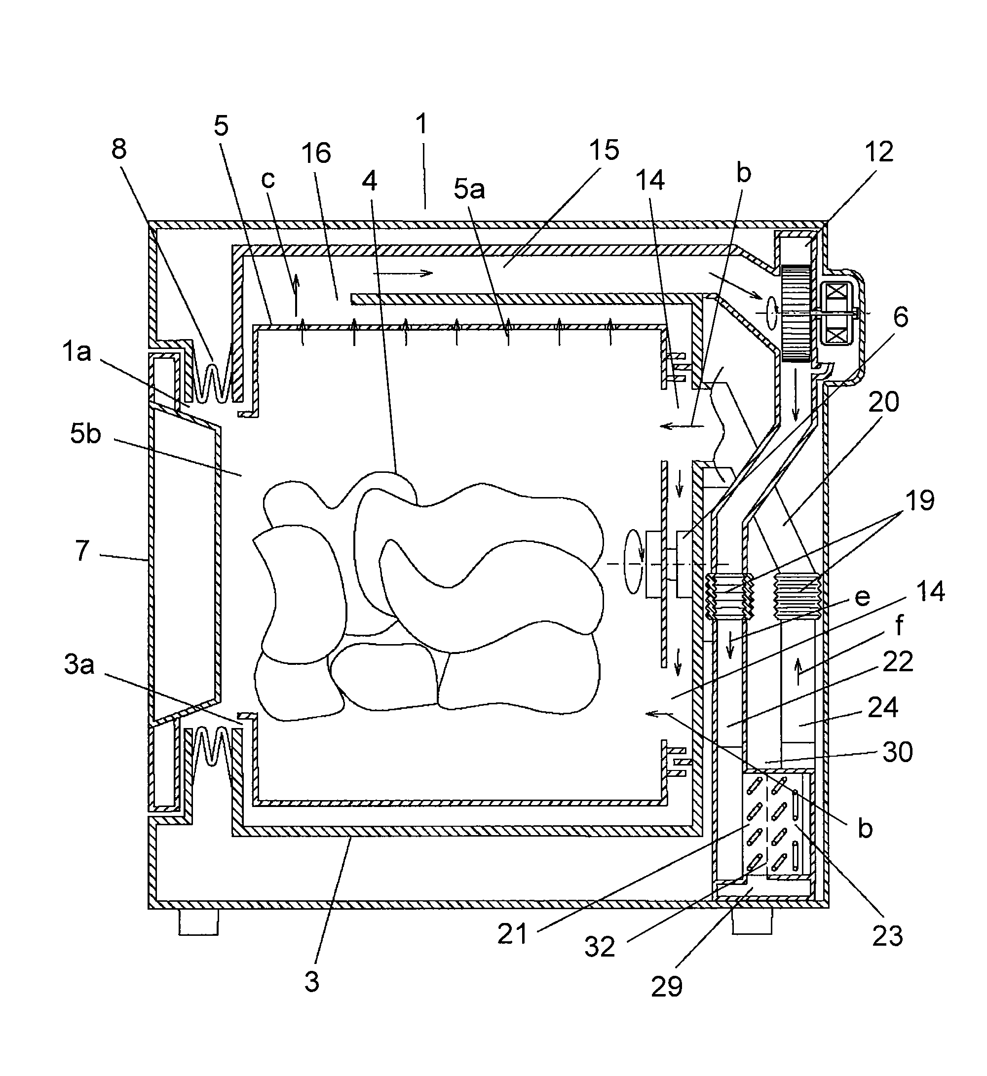
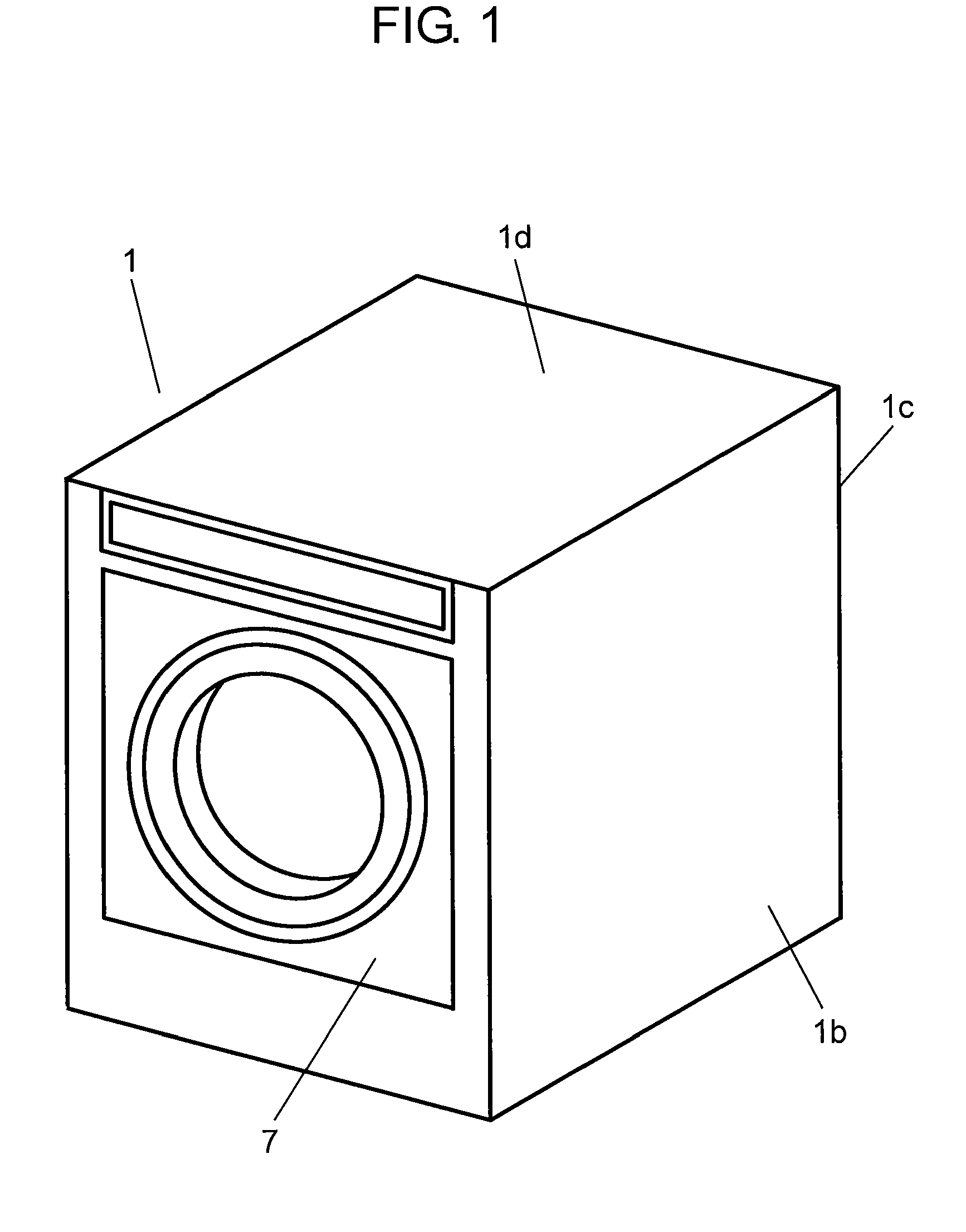
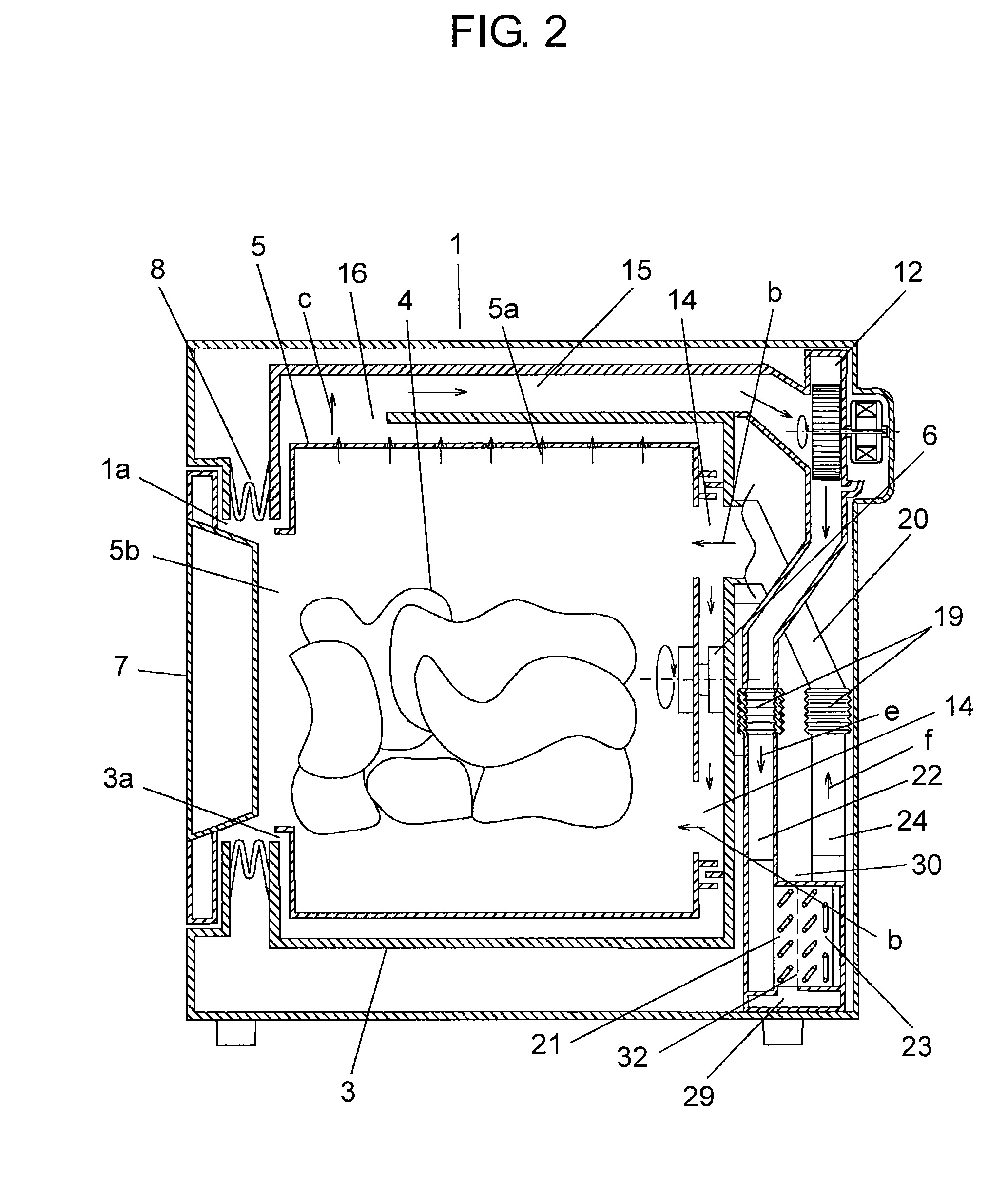
[0083]FIG. 1 shows a perspective appearance of a washer / dryer including a cloth dryer in accordance with the first embodiment of the present invention. FIG. 2 shows a sectional view of the washer / dryer shown in FIG. 1 and in drying operation, the washer / dryer is partially cut-away and viewed from right lateral face 1b of the housing. FIG. 3 shows the washer / dryer shown in FIG. 1 and in drying operation, the washer / dryer is partially cut-away and viewed from rear face 1c of the housing. FIG. 4 schematically illustrates a structure of a heat pump mounted in the washer / dryer and the flow of drying air. FIG. 5 shows an enlarged sectional view of a heat exchange air-flow path running in the washer / dryer.
[0084]As shown in FIG. 1-FIG. 5, housing 1 of the washer / dryer includes cylindrical water tub 3 therein resiliently supported by multiple suspensions 2, which absorb the vibration of water tub 3 during washing or spin-drying operation.
[0085]Water tub 3 includes cylindrical rotary tub 5 th...
embodiment 2
[0116]FIG. 6 shows an enlarged sectional view of a heat exchange air-flow path of a washer / dryer in accordance with the second embodiment of the present invention. Elements similar to those in embodiment 1 have the same reference signs and the descriptions thereof in detail are omitted here.
[0117]In this second embodiment, heat absorber 21 and heat radiator 23 are placed slantingly such that the lowest portion of heat absorber 21 is located somewhat lower than the lowest portion of heat radiator 23. This structure allows preventing the dew water formed on absorber 21 from moving toward radiator 23, so that the dew water attached to absorber 21 can travel smoothly to water reservoir 29. As a result, heat radiator 23 can be prevented from lowering the temperature due to water-splash from absorber 21 to radiator 23, and a washer / dryer excellent in drying efficiency is obtainable.
[0118]In a case where a heat exchanger or fin 25 differing in shape is used, a slant placement of heat absor...
embodiment 3
[0119]FIG. 7 shows an enlarged sectional view of a heat exchange air-flow path of a washer / dryer in accordance with the third embodiment of the present invention. Elements similar to those in embodiment 1 have the same reference signs and the descriptions thereof in detail are omitted here.
[0120]In this third embodiment, the placement of refrigerant pipe 21a of heat absorber 21 is the same as heat radiator 23. To be more specific, there are two rows of pipes 21a, namely one row extends vertically and includes refrigerant pipe 21a slanting, forming meanders, and running through fins 25, and the other row runs through fins 25, stands upright, and extends vertically. However, the refrigerant pipe belonging to the row standing upright and extending vertically is cancelled, and through-hole 33 left vacant intentionally (the refrigerant pipe does not run through).
[0121]The foregoing structure allows leaving a large space between absorber 21 and radiator 23, so that the dew water generated...
PUM
 Abstract
Description
Claims
Application Information
 - R&D
- Intellectual Property
- Life Sciences
- Materials
- Tech Scout
- Unparalleled Data Quality
- Higher Quality Content
- 60% Fewer Hallucinations
Browse by: Latest US Patents, China's latest patents, Technical Efficacy Thesaurus, Application Domain, Technology Topic, Popular Technical Reports.
© 2025 PatSnap. All rights reserved.Legal|Privacy policy|Modern Slavery Act Transparency Statement|Sitemap|About US| Contact US: help@patsnap.com


