Motor controlling apparatus
- Summary
- Abstract
- Description
- Claims
- Application Information
AI Technical Summary
Benefits of technology
Problems solved by technology
Method used
Image
Examples
Embodiment Construction
[0061]A motor controlling apparatus according to an exemplary embodiment of the present invention will now be explained based on the drawings. Note that the embodiment is not intended to limit the scope of the present invention in any way.
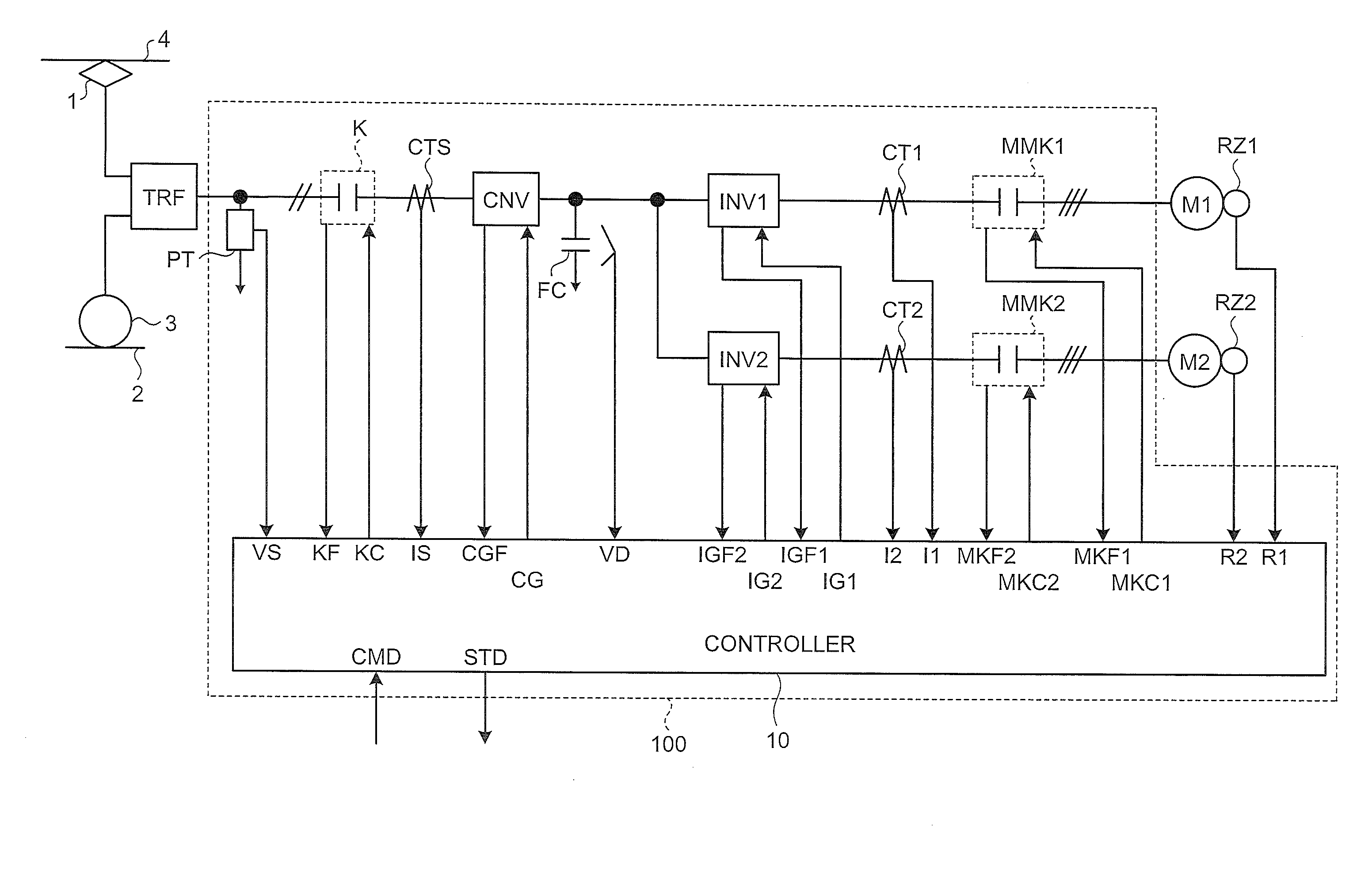
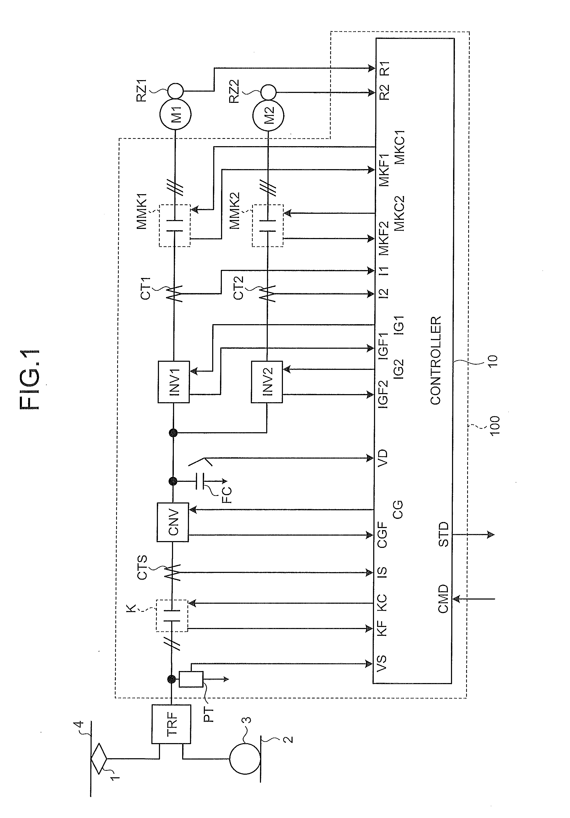
[0062]FIG. 1 is a schematic of a motor controlling apparatus according to an exemplary embodiment of the present invention. In this schematic, a controlling apparatus 100 according to the embodiment includes, sequentially from an input-stage side thereof, an input voltage detector PT, an input-side contactor K, an input current sensor CTS, a converter CNV, a filter capacitor FC, a first and a second inverters INV1 and INV2, a first and a second motor current sensors CT1 and CT2, and a first and a second motor-side contactors MMK1 and MMK2.
[0063]Furthermore, as shown in FIG. 1, the primary-side end of a transformer TRF is connected to an electric wire 4 via a power collector 1, and the other end is connected to a rail 2 that is at a ground potential...
PUM
 Abstract
Description
Claims
Application Information
 - R&D
- Intellectual Property
- Life Sciences
- Materials
- Tech Scout
- Unparalleled Data Quality
- Higher Quality Content
- 60% Fewer Hallucinations
Browse by: Latest US Patents, China's latest patents, Technical Efficacy Thesaurus, Application Domain, Technology Topic, Popular Technical Reports.
© 2025 PatSnap. All rights reserved.Legal|Privacy policy|Modern Slavery Act Transparency Statement|Sitemap|About US| Contact US: help@patsnap.com


