
Packaged power switching device

a power switching device and packaging technology, applied in the direction of electronic switching, semiconductor/solid-state device details, pulse technique, etc., can solve the problems of consuming some area, affecting the performance of the converter, and increasing the footprint of the modul

Inactive Publication Date: 2010-07-08
CICLON SEMICON DEVICE
View PDF25 Cites 70 Cited by
  • Summary
  • Abstract
  • Description
  • Claims
  • Application Information

AI Technical Summary

Problems solved by technology

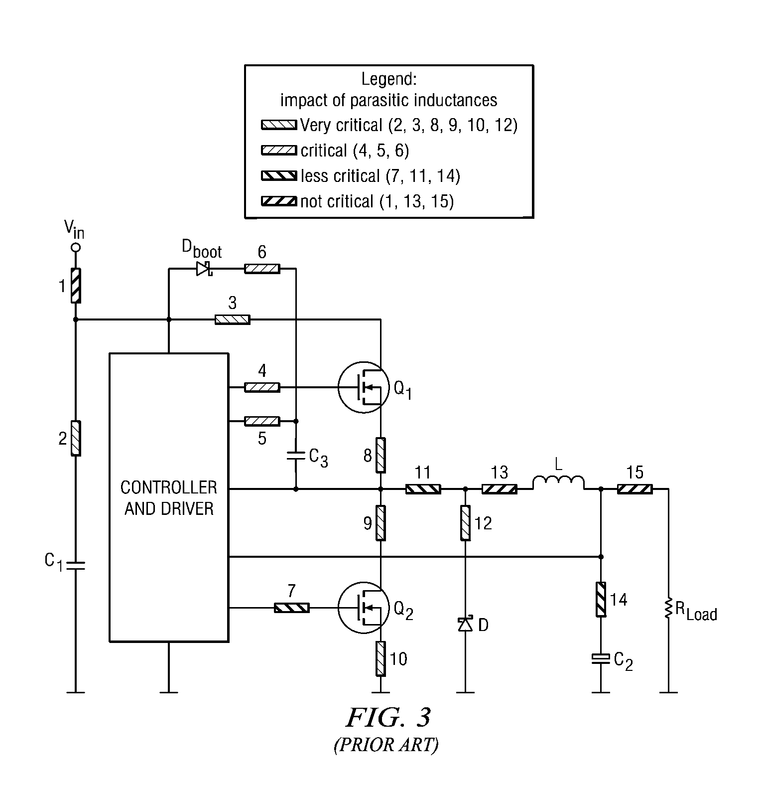
As explained by J. Hancock in his ITS'2003 Presentation, parasitic inductances introduced by the assembly of the push-pull stage have a detrimental impact on the performance of the converter.
This approach consumes some area and increases the footprint of the module.
However, monolithic power IC implementation is very expensive and complicated, making this approach prohibitive for most power electronics applications.

Method used


Image

  • Packaged power switching device
  • Packaged power switching device
  • Packaged power switching device

Examples


Embodiment Construction

[0028]This description of the exemplary embodiments is intended to be read in connection with the accompanying drawings, which are to be considered part of the entire written description. In the description, relative terms such as “lower,”“upper,”“horizontal,”“vertical,”“above,”“below,”“up,”“down,”“top” and “bottom” as well as derivative thereof (e.g., “horizontally,”“downwardly,”“upwardly,” etc.) should be construed to refer to the orientation as then described or as shown in the drawing under discussion. These relative terms are for convenience of description and do not require that the apparatus be constructed or operated in a particular orientation. Terms concerning attachments, coupling and the like, such as “connected” and “interconnected,” refer to a relationship wherein structures are secured or attached to one another either directly or indirectly through intervening structures, as well as both movable or rigid attachments or relationships, unless expressly described otherw...


PUM


Abstract

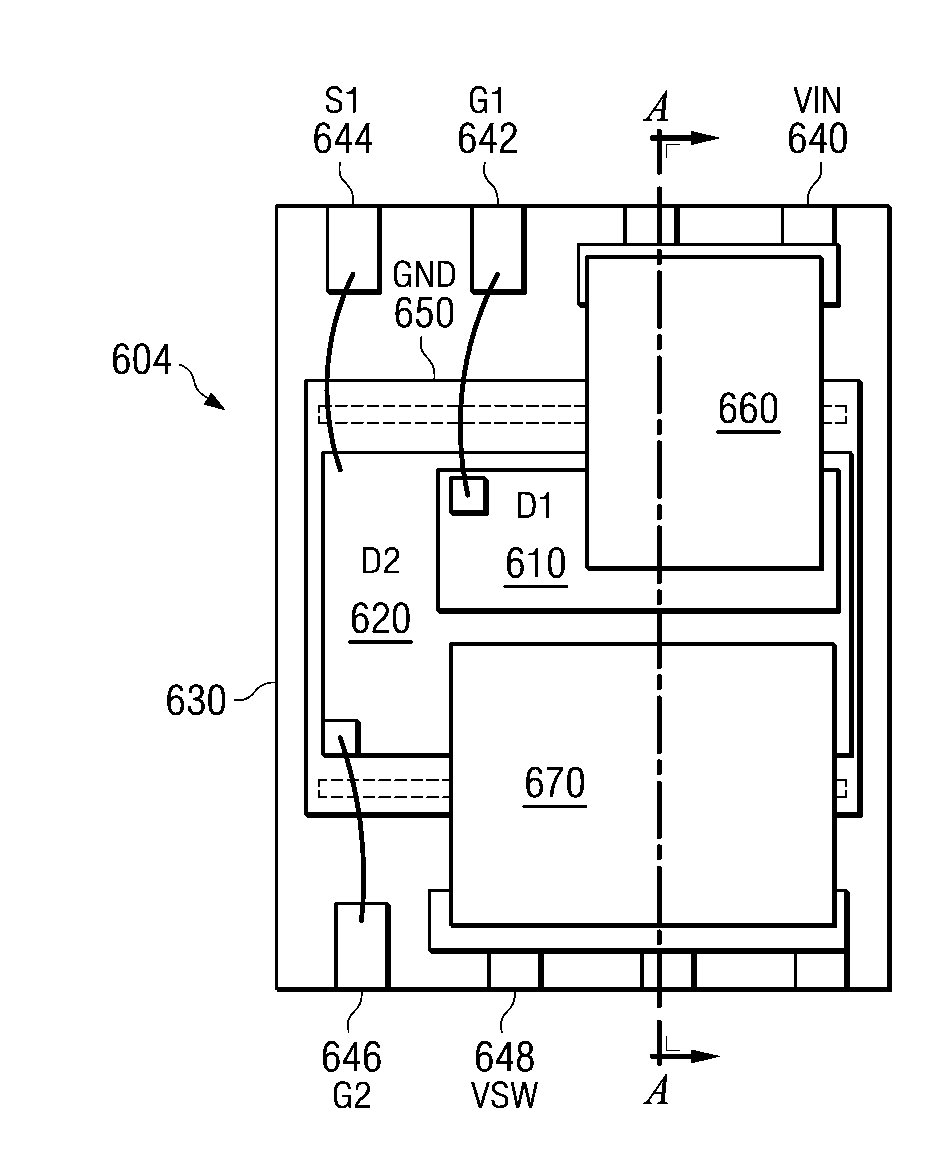
A packaged switching device for power applications includes at least one pair of power MOSFET transistor dies connected between upper and lower power source rail leads, a high side one of the pair of MOSFET transistor dies being connected to the upper power source rail lead and a low side one of the pair of MOSFET transistor dies being connected to the lower power source rail lead. At least one of the MOSFET transistor dies is configured for vertical current flow therethrough and has a source electrode at a backside thereof.

Description

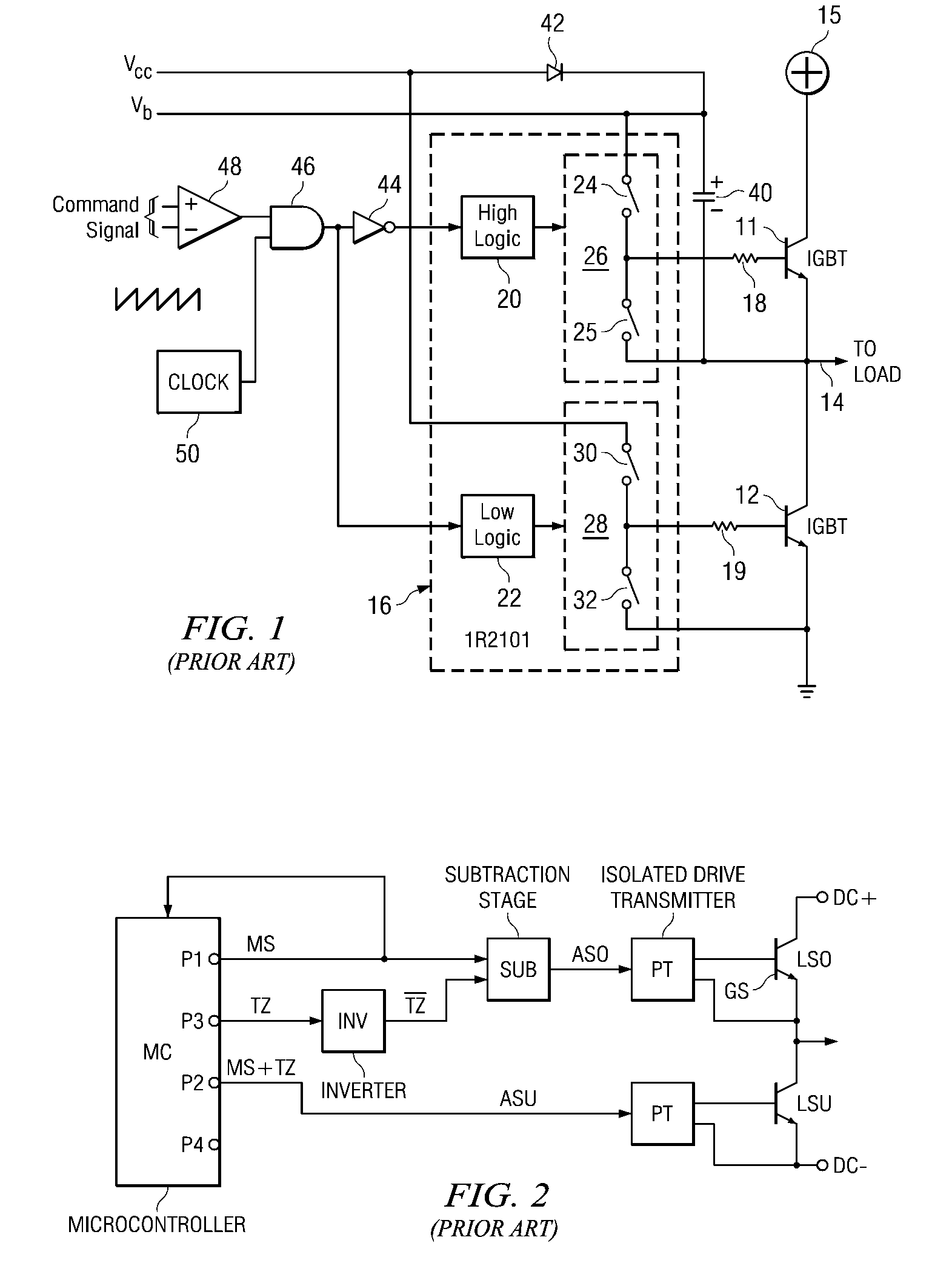
FIELD OF THE INVENTION[0001]The present invention relates to semiconductor devices and more particularly to power MOSFET devices.BACKGROUND OF THE INVENTION[0002]Power switching devices connected in pairs in a totem pole fashion between the upper and lower rails of the power source are common in power electronics applications as described in, for example, U.S. Pat. No. 6,246,296 to Smith, the entirety of which is hereby incorporated by reference herein. As shown in FIG. 1 of Smith (reprinted as FIG. 1 of this application) for the case of two insulated-gate bipolar transistor (IGBT) devices, one switch is connected between the supply voltage and the load connector and the second switch is connected between the load connector and ground. The totem pole configuration of the switches is a basic element of the majority of Pulse Width Modulation (PWM) systems like Switched Mode Power Supply (SMPS) or motor control schemes.[0003]The same configuration of two power switches implemented in a...

Claims


Application Information

Patent Timeline
Patent Type & Authority Applications(United States)
IPC IPC(8): H03K17/687H01L29/94H01L23/495
CPCH01L23/49524H01L2224/84801H01L23/49575H01L24/40H01L24/49H01L2224/48091H01L2224/48247H01L2224/49171H01L2224/49431H01L2224/73219H01L2924/01005H01L2924/01013H01L2924/01014H01L2924/01015H01L2924/01022H01L2924/01027H01L2924/01028H01L2924/01029H01L2924/01047H01L2924/01074H01L2924/01082H01L2924/13055H01L2924/13091H01L2924/14H01L2924/19041H01L2924/19042H01L2924/30107H01L2924/3025H03K17/6871H01L23/49562H01L24/41H01L24/37H01L2224/40245H01L2924/12036H01L2924/181H01L2924/1305H01L2224/40095H01L24/48H01L2924/01033H01L2924/014H01L2224/73221H01L2224/40247H01L2924/10253H01L2224/37147H01L24/45H01L2924/00014H01L2224/40137H01L2224/40139H01L2224/45147H01L2924/00H01L2224/05599H01L2924/00012H01L24/84
Inventor KOREC, JACEKBULL, CHRISTOPHER F.HERBSOMMER, JUAN ALEJANDROJAUREGUI, DAVIDKOCON, CHRISTOPHER B.
Owner CICLON SEMICON DEVICE
Learn More