Projection stereoscopic display

a stereoscopic display and projection technology, applied in the field of projection stereoscopic displays, can solve the problems achieve the effects of increasing the number of components and light loss, reducing power consumption, and high light condensing property

Inactive Publication Date: 2010-07-08
SONY CORP
View PDF8 Cites 20 Cited by
  • Summary
  • Abstract
  • Description
  • Claims
  • Application Information

AI Technical Summary

Benefits of technology

[0008]However, in the case where a polarized light source such as a laser is used, it is necessary to convert light into a non-polarization state in advance, thereby the number of components and light loss increase. A laser light source has lower power consumption than a lamp or a light-emitting diode, and has a high light condensing property and extremely high color purity, so a projector with higher efficiency and a wide color gamut is achievable. Moreover, by the above-described pr

Problems solved by technology

However, in the case where a polarized light source such as a laser is used, it is necessary to convert

Method used


Image

  • Projection stereoscopic display
  • Projection stereoscopic display
  • Projection stereoscopic display

Examples


first embodiment

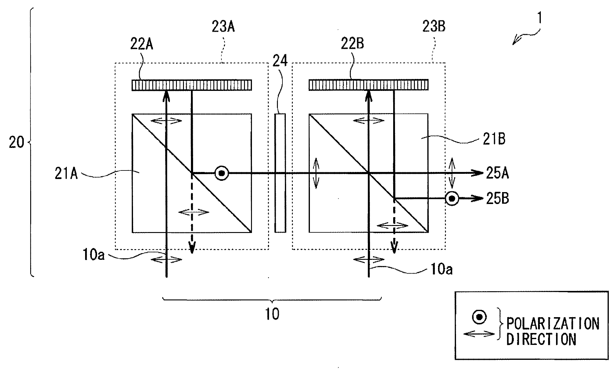
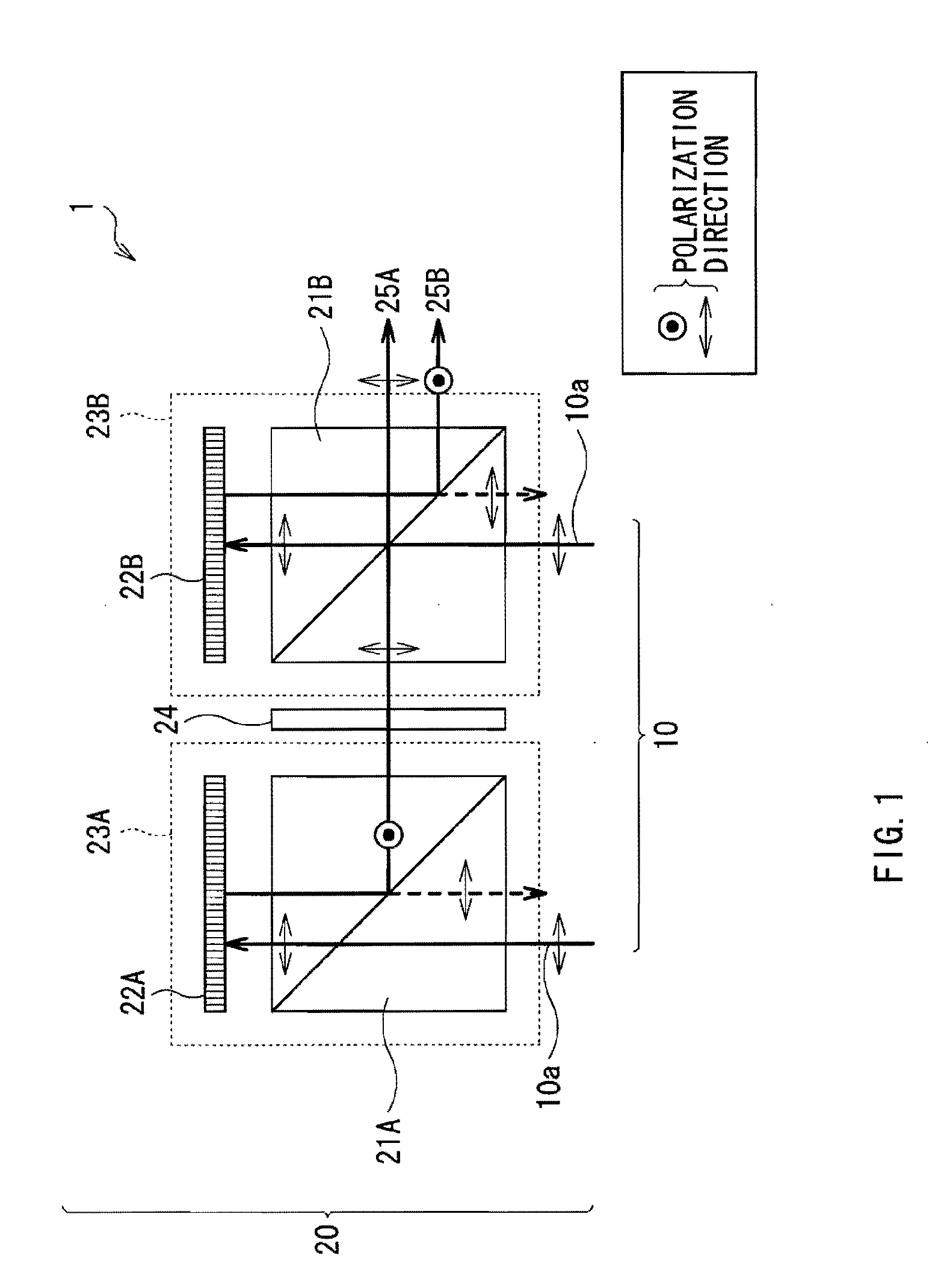
[0022]FIG. 1 illustrates a configuration of a projection stereoscopic display (hereinafter referred to as stereoscopic display) 1 according to a first embodiment of the invention. The stereoscopic display 1 stereoscopically displays a picture based on an input picture signal supplied from outside, and roughly includes a light source 10 and a stereoscopic display optical system 20.

[0023]The light source 10 is a laser (a LD or a solid-state laser), and laser light 10a from the light source 10 includes, for example, a linearly polarized component (a first linearly polarized component) in a direction parallel to a paper plane (in a direction indicated by arrows in the drawing).

[0024]The stereoscopic display optical system 20 includes a first modulation section 23A which is configured of a first polarizing beam splitter 21A and a first reflective liquid crystal panel 22A, and a second modulation section 23B which is configured of a second polarizing beam splitter 21B and a second reflect...

application example 1

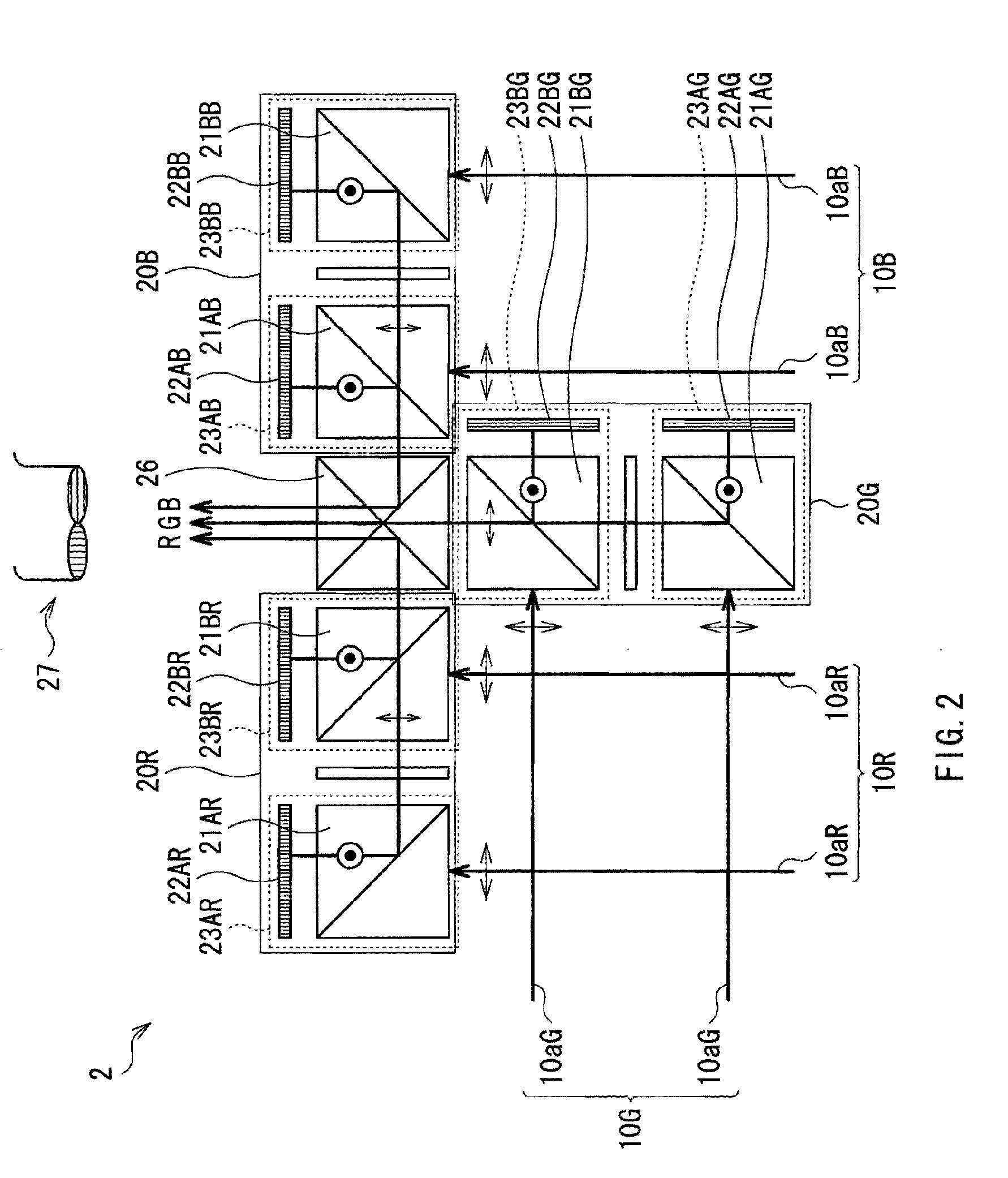
[0035]A stereoscopic display 2 illustrated in FIG. 2 has a configuration in which stereoscopic display optical systems 20 in the above-described stereoscopic display 1 are combined to allow color display of three primary colors R (red), G (green) and B (blue). In this case, reference numerals for components are denoted corresponding to the colors RGB such as, for example, stereoscopic display optical systems 20R, 20G and 20B. The stereoscopic display 2 includes the stereoscopic display optical systems 20R, 20G and 20B and a multiplexing prism 26 for combining pictures of these colors emitted from the stereoscopic display optical systems 20R, 20G and 20B.

[0036]In other words, in the stereoscopic display 2, as in the case of the above-described embodiment, the stereoscopic display optical system 20R into which red laser light 10aR has entered emits a red picture formed by superimposing right and left pictures. Likewise, the stereoscopic display optical system 20G into which green lase...

second embodiment

[0037]FIG. 3 illustrates a configuration of a stereoscopic display 3 according to a second embodiment of the invention. The stereoscopic display 3 has a configuration in which the first polarizing beam splitter 21A in the first embodiment is replaced with a wire grid polarizer 30, and the λ / 2 wave plate 24 is arranged in a position anterior to the wire grid polarizer 30. Other configurations, and functions and effects are the same as those in the above-described embodiment. Very thin metallic wires are formed on a surface of the wire grid polarizer 30 in a direction parallel to a paper plane, and the wire grid polarizer 30 allows light with a polarization direction perpendicular to the paper plane to pass therethrough, and reflects light with a polarization direction parallel to the paper plane.

[0038]In the embodiment, before the laser light 10a enters into the wire grid polarizer 30, the polarization direction of the laser light 10a is converted by the λ / 2 wave plate 24 so that the...


PUM


Abstract

A projection stereoscopic display includes: a stereoscopic display optical system receiving linearly polarized light from the light source and displaying a first picture and a second picture both having binocular parallax by linearly polarized light with polarization directions orthogonal to each other, in which the stereoscopic display optical system includes: a reflective liquid crystal panel modulating and reflecting linearly polarized light from the light source in response to a picture signal, a first polarizing device splitting the first picture from reflected light from the reflective liquid crystal panel, a retardation device converting the polarization direction of the first picture into a direction orthogonal thereto, and a second polarizing device splitting the second picture from reflected light from the reflective liquid crystal panel, and superimposing the second picture on the first picture of which the polarization direction is converted by the retardation device.

Description

BACKGROUND OF THE INVENTION[0001]1. Field of the Invention[0002]The present invention relates to a projection stereoscopic display including an optical system which includes a reflective liquid crystal panel and a polarizer.[0003]2. Description of the Related Art[0004]There are projection stereoscopic displays providing independent images to the right eye and the left eye of a viewer, respectively, to allow stereoscopic vision using binocular parallax, and various systems of projection stereoscopic displays have been proposed. For example, two projection displays (projectors) are used to superimpose a right-eye picture and a left-eye picture with orthogonal polarization directions on each other and project them, and when the viewer wearing a pair of glasses which use polarizing plates with orthogonal polarization directions as right-eye and left-eye lenses views the pictures, the viewer are allowed to experience stereoscopic vision.[0005]Moreover, for example, as described in Japane...

Claims


Application Information

Patent Timeline
IPC IPC(8): G02F1/13363G02B27/26G02B30/25
CPCG02B27/26G02F1/133528G02B30/25
Inventor FURUKAWA, AKIOTAKIGUCHI, YOSHIRO
Owner SONY CORP
Why Eureka
Try Eureka