Stator Casing Having Improved Running Clearances Under Thermal Load

a technology of thermal load and stator, which is applied in the direction of machines/engines, stators, liquid fuel engines, etc., can solve the problems of reducing the efficiency of the engine, the contact between the rotor and the stator the thermal response rate mismatch is the most severe, so as to improve the efficiency of the gas turbine engine and reduce the inner diameter of the shroud

Inactive Publication Date: 2010-07-08
GENERAL ELECTRIC CO
View PDF3 Cites 15 Cited by
  • Summary
  • Abstract
  • Description
  • Claims
  • Application Information

AI Technical Summary

Benefits of technology

[0009]In one aspect, the present invention comprises a turbine power generation system, comprising a stator including a shroud and a rotor rotatably situated within the shroud, wherein the shroud is structured such that the inner diameter of the inner surface of the shroud reduces when the inner surface is exposed to a thermal load.
[0011]In yet another aspect, the present invention comprises a method for improving efficiency of a gas turbine engine comprising the steps of: (1) providing a shroud for the stator; (2) firing the gas turbine engine to produce heat within the shroud; and (3) applying the heat produced by the gas turbine engine to the shroud so as to reduce the inner diameter of the shroud.

Problems solved by technology

As clearance increases, more of the engine air passes around the blade tips of the turbine or compressor and the casing without producing useful work, decreasing the engine's efficiency.
Too small of a clearance results in contact between the rotor and stator in certain operating conditions.
The thermal response rate mismatch is most severe for many gas turbine engines during shutdown.
This is because rotor purge circuits do not have a sufficient pressure difference to drive cooling flow.

Method used


Image

  • Stator Casing Having Improved Running Clearances Under Thermal Load
  • Stator Casing Having Improved Running Clearances Under Thermal Load
  • Stator Casing Having Improved Running Clearances Under Thermal Load

Examples


Embodiment Construction

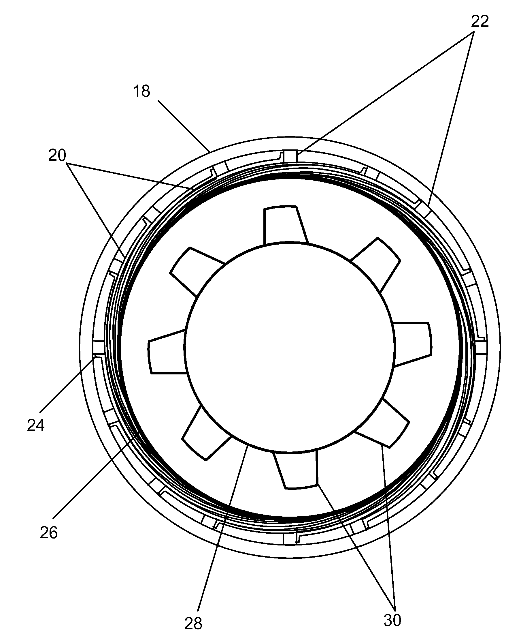
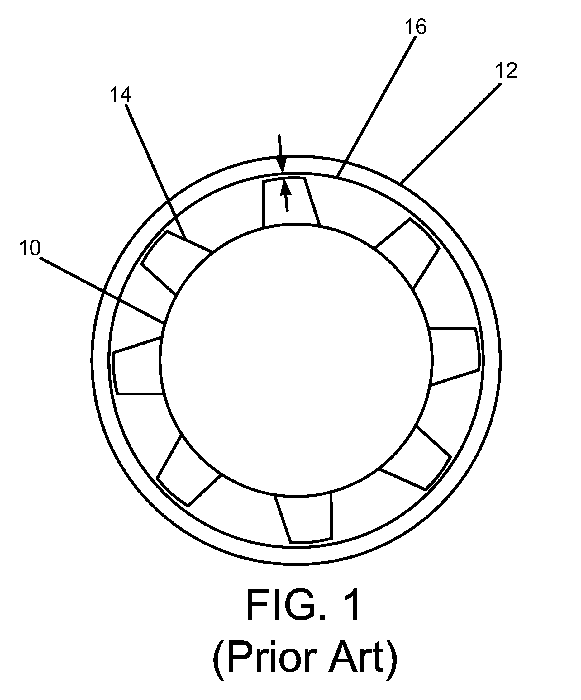
[0019]FIG. 1 is a depiction of a simplified rotor situated within a stator casing. The rotor 10 includes a plurality of blades 14 which are circumferentially situated about the rotor 10. The blades 14 extend in a radial direction from the axis of rotation of the rotor 10 toward the inner surface 16 of the casing of the stator 12. The portion of the blade 14 closest to the inner surface 16 is referred to as the “tip.” The clearance between the blade 14 and the inner surface 16 is illustrated by the arrows in FIG. 1. As explained previously, the greatest efficiency is achieved when operating at minimal clearance. This clearance changes as the turbine undergoes transient operations because of the differing thermal response rates of the stator 12 and the rotor 10.

[0020]Once a turbine is fired, rotation of the rotor 10 causes mechanical deflection of the blades 14 as rotational forces pull the blades 14 towards the inner surface 16. As thermal loads are applied, the rotor 10 and the stat...


PUM


Abstract

A turbine power generation system, comprising a stator including a shroud and a rotor rotatably situated within the shroud, wherein the shroud is structured such that the inner diameter of the inner surface of the shroud reduces when the inner surface is exposed to a thermal load. The reduction of the inner diameter allows a minimum blade-casing clearance to be achieved during steady-state operation instead of during transient operations. Blade-casing clearance is configured to be greatest at when the engine is in a cold, stationary position. The clearance is further configured to decrease as thermal load increases until a steady-state, thermal equilibrium is achieved. The clearance grows during shutdown as the stator and rotor begin to cool.

Description

CROSS REFERENCE TO RELATED APPLICATIONS[0001]Not applicable.STATEMENT REGARDING FEDERALLY SPONSORED RESEARCH OR DEVELOPMENT[0002]Not applicable.BACKGROUND OF THE INVENTION[0003]This invention is generally in the field of gas turbine power generation systems. More particularly, the present invention is directed to a stator casing having improved running clearances under thermal load.[0004]Combustion turbines are often part of a power generation unit. The components of such power generation systems usually include the turbine, a compressor, and a generator. These components are mechanically linked, often employing multiple shafts to increase the unit's efficiency. The generator is generally a separate shaft driven machine. Depending on the size and output of the combustion turbine, a gearbox is sometimes used to couple the generator with the combustion turbine's shaft output.[0005]Generally, combustion turbines operate in what is known as a Brayton Cycle. The Brayton cycle encompasses...

Claims


Application Information

Patent Timeline
Patent Type & Authority Applications(United States)
IPC IPC(8): F01D1/02
CPCF05D2240/57F01D11/18F05D2240/59
Inventor FLANAGAN, MARK W.
Owner GENERAL ELECTRIC CO
Why Eureka
Try Eureka