Gas generation apparatus

a technology of gas generation apparatus and gas, which is applied in the direction of fluid pressure control, physical/chemical process catalysts, instruments, etc., can solve the problems of large scale, complicated apparatus, and difficulty in stopping generating hydrogen gas

Inactive Publication Date: 2010-07-08
MITSUBISHI PENCIL CO LTD
View PDF5 Cites 12 Cited by
  • Summary
  • Abstract
  • Description
  • Claims
  • Application Information

AI Technical Summary

Benefits of technology

[0012]According to the present invention, provided is a gas generation apparatus in which generation of gas can automatically be controlled by a simple mechanism when the gas is not consumed, so that excess gas can be inhibited from being generated.
[0013]FIG. 1 is an outline cross-sectional drawing of a gas generation apparatus showing one example of the embodiments of the present invention.
[0014]FIG. 2 is a vertical cross-sectional drawing of the gas generation apparatus.
[0015]FIG. 3 is a vertical cross-sectional drawing f

Problems solved by technology

However, the hydrogen generation apparatus described in patent document 1 has the problem that it is difficult to stop generating hydrogen gas once generation of hydrogen gas starts and that it is difficult as well to stop generating hydrogen gas, for example, even after stopping the operation of the apparatus.
In this case, however, the apparatus is large-scaled and complicated, and therefore it is unsuited for a small-sized hydrogen generation apparatus and a fuel generation apparatus of fuel cells for portable devices.
However, involved therein is the problem that continuous supply of hydrog

Method used


Image

  • Gas generation apparatus
  • Gas generation apparatus
  • Gas generation apparatus

Examples


example 1

[0052]A gas generation apparatus was obtained by the following production process, and then a hydrogen generation amount thereof was evaluated.

Production of Apparatus Main Body:

[0053]Outer dimension: φ16×15 mm[0054]Inner dimension: φ14×11 mm[0055]Material: made of a vinyl chloride resin

Lid Main Body:

[0056]Dimension: φ14×5 mm[0057]Material: made of a vinyl chloride resin

Sealing Valve:

[0058]Dimension: major diameter 5 mm×minor diameter 4 mm[0059]Material: made of butyl rubber

Mounting Member:

[0060]Dimension: φ4×2 mm[0061]Material: made of a vinyl chloride resin

Gas Supplying Tube:

[0062]Dimension: outer diameter: φ1×15 mm, inner diameter: φ0.7×15 mm[0063]Material: made of stainless

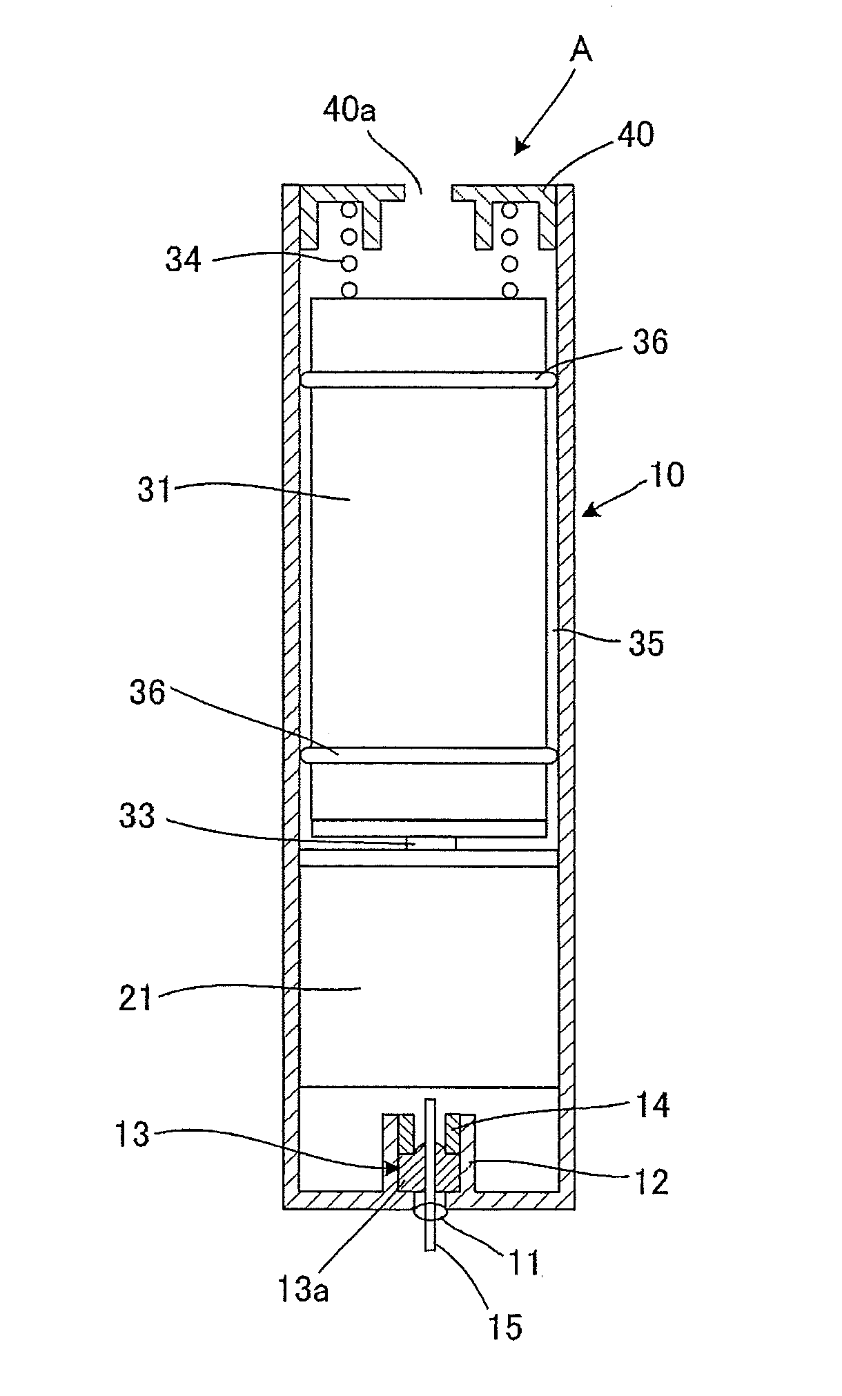
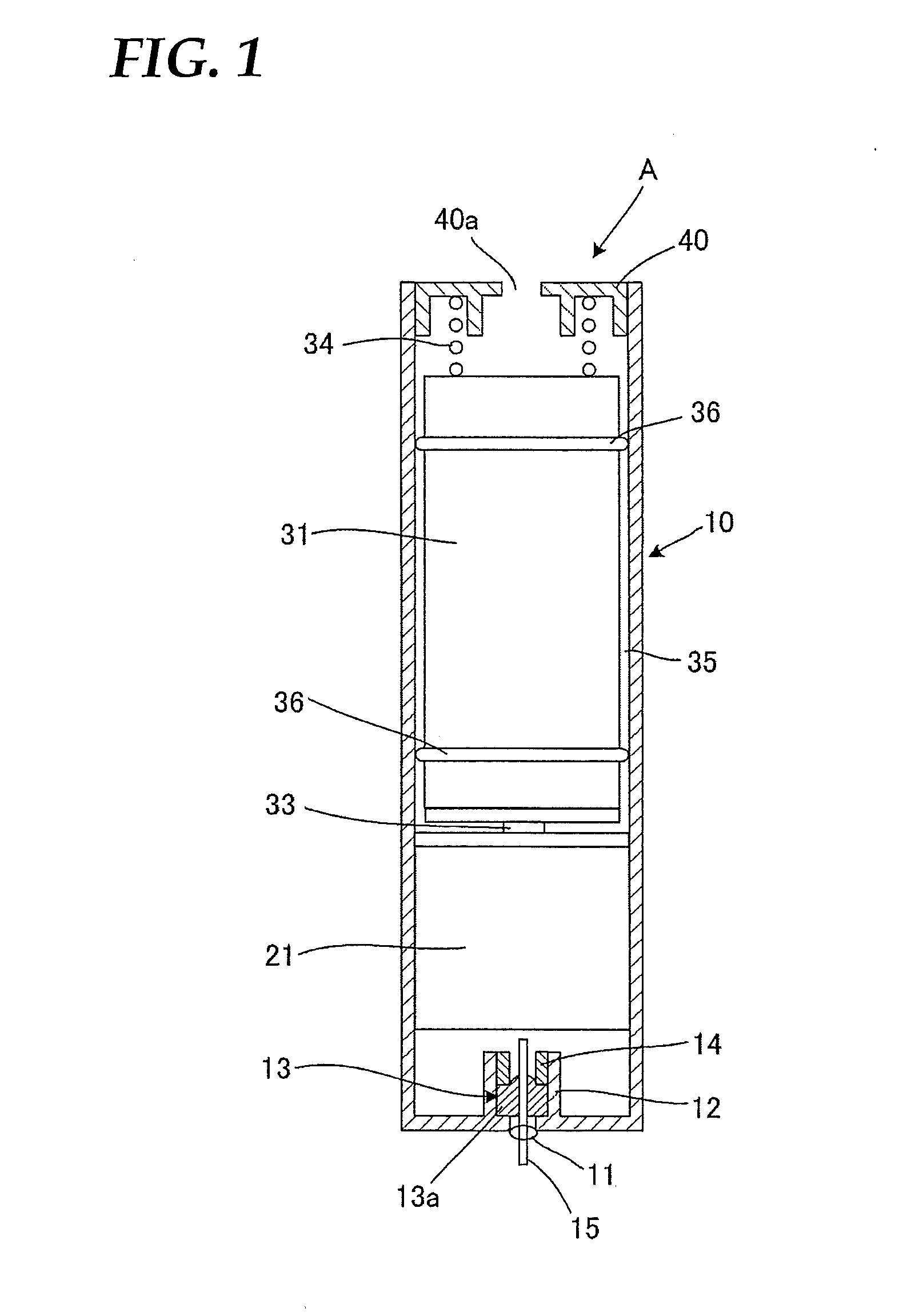
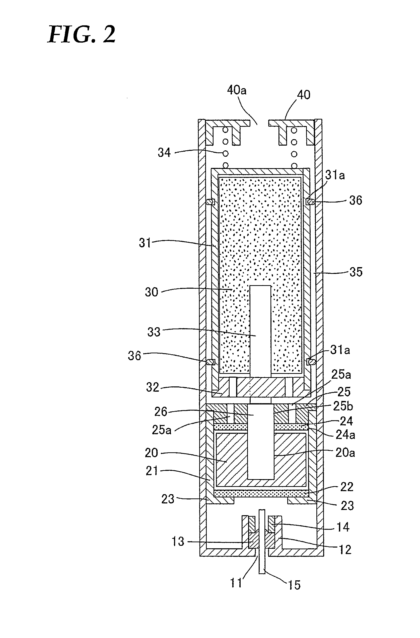
Production of Gas Generating Agent-Storing Vessel: Conforming to FIG. 1 to FIG. 3

Gas Generating Agent-Storing Vessel:

[0064]Outer dimension: φ16×15 mm[0065]Inner dimension: φ14×11 mm[0066]Material: made of a vinyl chloride resin

Lower and Upper Filter Members: Porous Bodies (Pore Diameter: 100 μm) Made of a Fluor...


PUM

PropertyMeasurementUnit
Forceaaaaaaaaaa
Pressureaaaaaaaaaa

Abstract

In order to provide a gas generation apparatus such as a hydrogen gas generation apparatus for a fuel cell or an oxygen gas generation apparatus used in medical sites and at the time of disasters in which a solid gas generating agent such as metal is brought into contact with a reaction liquid to generate hydrogen gas or oxygen gas, a gas generation apparatus A having a solid gas generating agent and a reaction liquid in which the solid gas generating agent and the reaction liquid are stored respectively in separate storing vessels 21, 31 and in which the reaction liquid is supplied into the gas generating agent-storing vessel to generate gas by capillary-active connection of the respective storing vessels assumes a constitution in which capillary-active connection is shut off when a pressure of the gas is raised. In the above gas generation apparatus, generation of the gas can automatically be controlled by a simple mechanism when the gas is not consumed, and therefore generation of excessive gas can be controlled.

Description

TECHNICAL FIELD[0001]The present invention relates to a gas generation apparatus in which a solid gas generating agent such as metal is brought into contact with a reaction liquid to generate hydrogen gas or oxygen gas, particularly to a gas generation apparatus useful as technology for supplying hydrogen gas to a fuel cell or a gas generation apparatus useful as an oxygen gas generation apparatus which is used for mental health care and in medical sites and at the time of disasters.BACKGROUND ART[0002]In recent years, a polymer electrolyte fuel cell (PECF) in which hydrogen gas is derived from metal and an aqueous solution and used as fuel is being actively developed as a fuel cell for portable devices.[0003]In general, a fuel cell of a type in which hydrogen is used as fuel is characterized in that it has a high output as compared with that of a direct methanol fuel cell (DMCF), and in addition thereto, it is characterized in that a power generation part itself can assume a simple...

Claims


Application Information

Patent Timeline
IPC IPC(8): B01J7/02C01B3/08C01B13/02G05D16/00B01J7/00
CPCC01B3/065C01B3/08C01B3/323C01B13/0214Y02E60/50H01M8/04208H01M8/065Y02E60/362C01B2203/066Y02E60/36Y02P20/52
Inventor KAMITANI, TOSHIMI
Owner MITSUBISHI PENCIL CO LTD
Why Eureka
Try Eureka