Method and System for Dynamic Spectrum Access

a dynamic spectrum and access technology, applied in the field of dynamic spectrum access, can solve the problems of not determining a new band or frequency range from which to search for channels, networked radios and other devices designed to operate within one particular channel or set of channels, and cannot automatically adapt to significant or challenging changes. the effect of measuring energy

Inactive Publication Date: 2010-07-08
SHARED SPECTRUM
View PDF99 Cites 279 Cited by
  • Summary
  • Abstract
  • Description
  • Claims
  • Application Information

AI Technical Summary

Benefits of technology

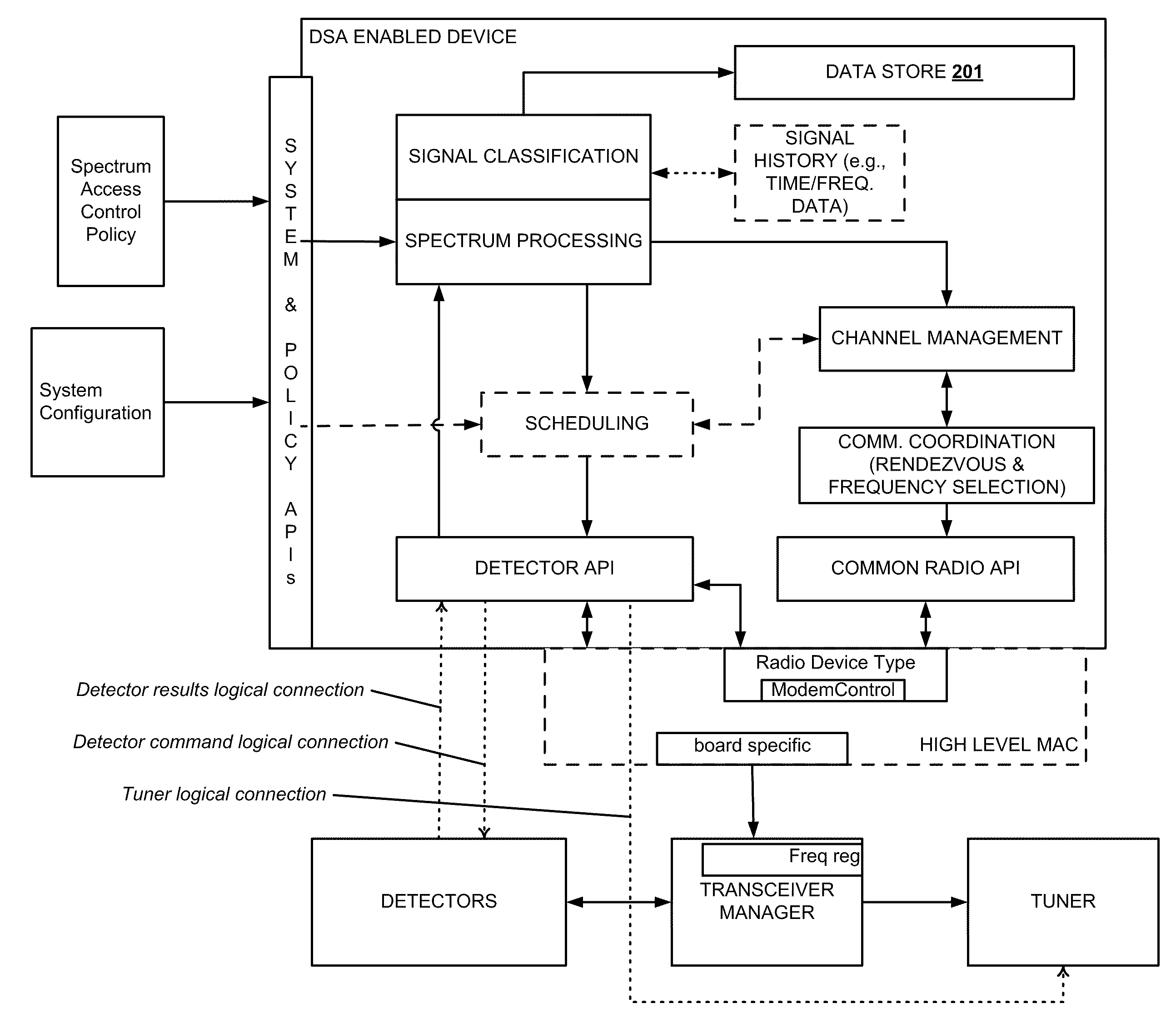
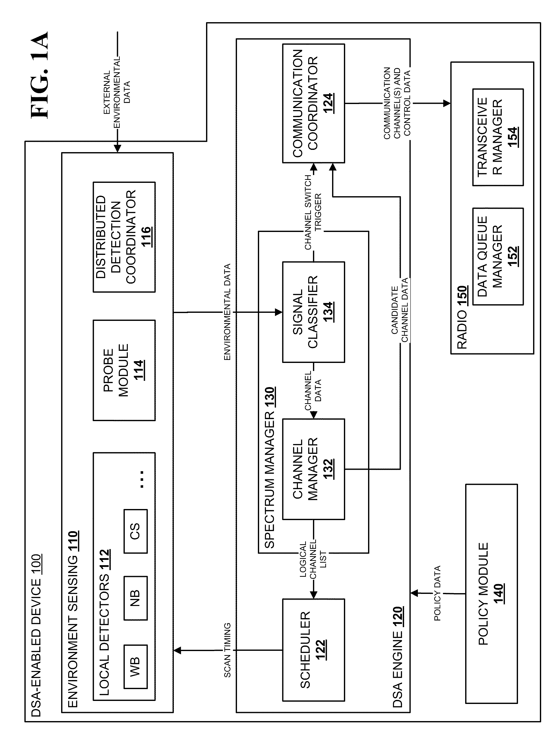
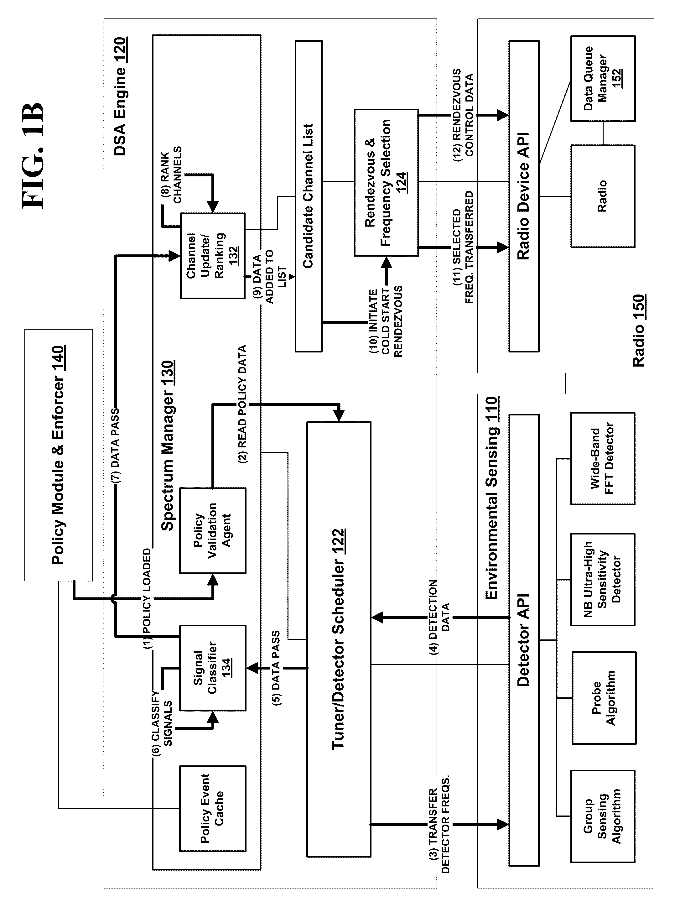
[0023]An aspect of the invention includes a method of identifying a cooperative signal by a dynamic spectrum access-enabled device, which may include measuring energy present in at least one of a first side portion and a second side portion of a narrow channel, the first side portion being defined by a first frequency range and the second side portion being defined a second frequency range higher than and non-overlapping with the first frequency range, setting an energy threshold to be the value of the energy measured in said side portion measuring step, measuring energy present in a central portion of the narrow channel, the central portion being defined by a central frequency range between the first and second frequency ranges, and,

Problems solved by technology

However, such devices are unable to automatically adapt to significant or challenging changes within the network or spectrum environment such as those discussed below.
Networked radios and other devices designed to operate within one particular channel or set of channels cannot operate outside of the designated channels without appropriate authorization from regulatory authorities or spectrum owners and/or modification of the radios.
Such a radio, however, does not determine a new band or frequency range from which to search for channels if a channel is not found.
Rather, the radio either works within its prescribed frequency band according to its fixed characteristics (such as transm

Method used


Image

  • Method and System for Dynamic Spectrum Access
  • Method and System for Dynamic Spectrum Access
  • Method and System for Dynamic Spectrum Access

Examples


example dsa

Receiver Configuration Table

[0377]

DSA Receiver SettingSignal of InterestPre-RFIFSub-F1F2SelectorATTATTADCband(MHz)(MHz)Band(dB)(dB)SHIFT1225235140022452551400325526511515242652751400527528514306285295140072953051400830531517009315325149010 325335140011 335345240012 34535524100. . .. . .. . .. . .. . .. . .. . .

[0378]The DSA transmitter hardware settings may be determined to obtain a desired transmit power level, such as by calibration using a spectrum analyzer. An output spectrum is measured for all RF and IF component settings and the measurements ordered by the transmit power level. For each output power level increment, the best spectrum is selected. The associated RF and IF component settings are then used as the table values. In an operational mode, the hardware settings may be changed during, for example, the 802.16 frame for the detector, the transmitter, and the receiver. Each of these operations may be performed at a different frequency. Periodically, during an operation mo...

example hardware

FUNCTIONAL DESCRIPTION

[0379]This section describes the examples of hardware modules and components that were built and used embodying at least portions of the DSA technology described herein. It will be understood that various combinations of hardware and / or software other than the specific examples described herein may be used without departing from the scope of the invention. For example, various hardware components may be combined, omitted, replaced, or otherwise altered from the following examples without changing the functionality or scope of the resulting system, as will be understood by one of skill in the art. Further, the various examples illustrate how DSA may be implemented on a variety of radio types, although types other than those specifically described may be used. Different MAC types (e.g., CSMA, TDMA and push-to-talk), detector types (e.g., FFT, cyclostationary, Ultra-Narrow bandwidth, and RSSI), and processors types (e.g., FPGA, DSP, GPP and limited capability proc...


PUM


Abstract

Methods and systems for dynamic spectrum access (DSA) in a wireless network are provided. A DSA-enabled device may sense spectrum use in a region and, based on the detected spectrum use, select one or more communication channels for use. The devices also may detect one or more other DSA-enabled devices with which they can form DSA networks. A DSA network may monitor spectrum use by cooperative and non-cooperative devices, to dynamically select one or more channels to use for communication while avoiding or reducing interference with other devices.

Description

RELATED APPLICATIONS[0001]This application claims priority to U.S. Application No. 61 / 090,076, filed Aug. 19, 2008, the disclosure of which is incorporated by reference in its entirety for all purposes; this application also is a continuation-in-part of the following applications: U.S. application Ser. No. 11 / 582,496, filed Oct. 18, 2006; U.S. application Ser. No. 11 / 783,563, filed Apr. 10, 2007, which claims priority to U.S. Provisional Application No. 60 / 877,656, filed Dec. 29, 2006; U.S. application Ser. No. 11 / 839,496, filed Aug. 15, 2007; U.S. application Ser. No. 11 / 839,503, filed Aug. 15, 2007; and U.S. application Ser. No. 12 / 487,257, filed Jun. 18, 2009, which is a continuation of U.S. application Ser. No. 11 / 432,536, filed May 12, 2006, now U.S. Pat. No. 7,564,816, the disclosure of each of which is incorporated by reference in its entirety for all purposes.STATEMENT AS TO RIGHTS TO INVENTIONS MADE UNDER FEDERALLY SPONSORED RESEARCH AND DEVELOPMENT[0002]This invention was ...

Claims


Application Information

Patent Timeline
IPC IPC(8): H04B17/00
CPCH04L27/0006H04W72/082H04W72/0406H04W16/14H04W72/20H04W72/541
Inventor MCHENRY, MARK ALLENBAZAROV, IGOR ANATOLYLIVSICS, JEVGENIJSPERICH, FILIPRITTERBUSH, OLGA K.STEADMAN, KARI N.
Owner SHARED SPECTRUM
Why Eureka
Try Eureka