Liquid injector, fluoroscopic imaging system, and computer program

a fluoroscopic imaging and liquid injector technology, applied in the field of liquid injectors, fluoroscopic imaging systems, computer programs, can solve the problems of inability to prevent injection to the patient based on inappropriate injection control data, complicated, difficult for unskilled operators to properly perform,

Inactive Publication Date: 2010-07-08
NEMOTO KYORINDO KK
View PDF11 Cites 60 Cited by
  • Summary
  • Abstract
  • Description
  • Claims
  • Application Information

AI Technical Summary

Benefits of technology

[0024]The present invention has been accomplished in view of the foregoing problem, with an object to provide a fluoroscopic imaging system that allows easily setting the injection control data that is appropriate for the patient, in the liquid injector.
[0041]With the liquid injector according to the present invention, once the patient ID and the injection control data are input and the liquid injection is executed, the injection control data and the injection history data are registered together with the patient ID. Then, when the same patient is to undergo the second or subsequent liquid injection, the previous injection control data and the injection history data are acquired based on the patient ID input, and are set as renewed injection control data. Such arrangement eliminates the need to repeat the input of the injection control data with respect to the same patient. Further, since the injection control data of each patient is registered and acquired based on the patient ID, the liquid injection to the patient based on erroneous setting of inappropriate injection control data can be automatically prevented.

Problems solved by technology

Such task is, however, so complicated that it is difficult for an unskilled operator to properly perform.
Besides, with the conventional liquid injector it is possible to execute the liquid injection only if the injection control data is available, even though the injection control data actually does not properly correspond to the patient who is to undergo the fluoroscopic image data pickup.
Therefore, injection to the patient based on inappropriate injection control data cannot be prevented.

Method used


Image

  • Liquid injector, fluoroscopic imaging system, and computer program
  • Liquid injector, fluoroscopic imaging system, and computer program
  • Liquid injector, fluoroscopic imaging system, and computer program

Examples


Embodiment Construction

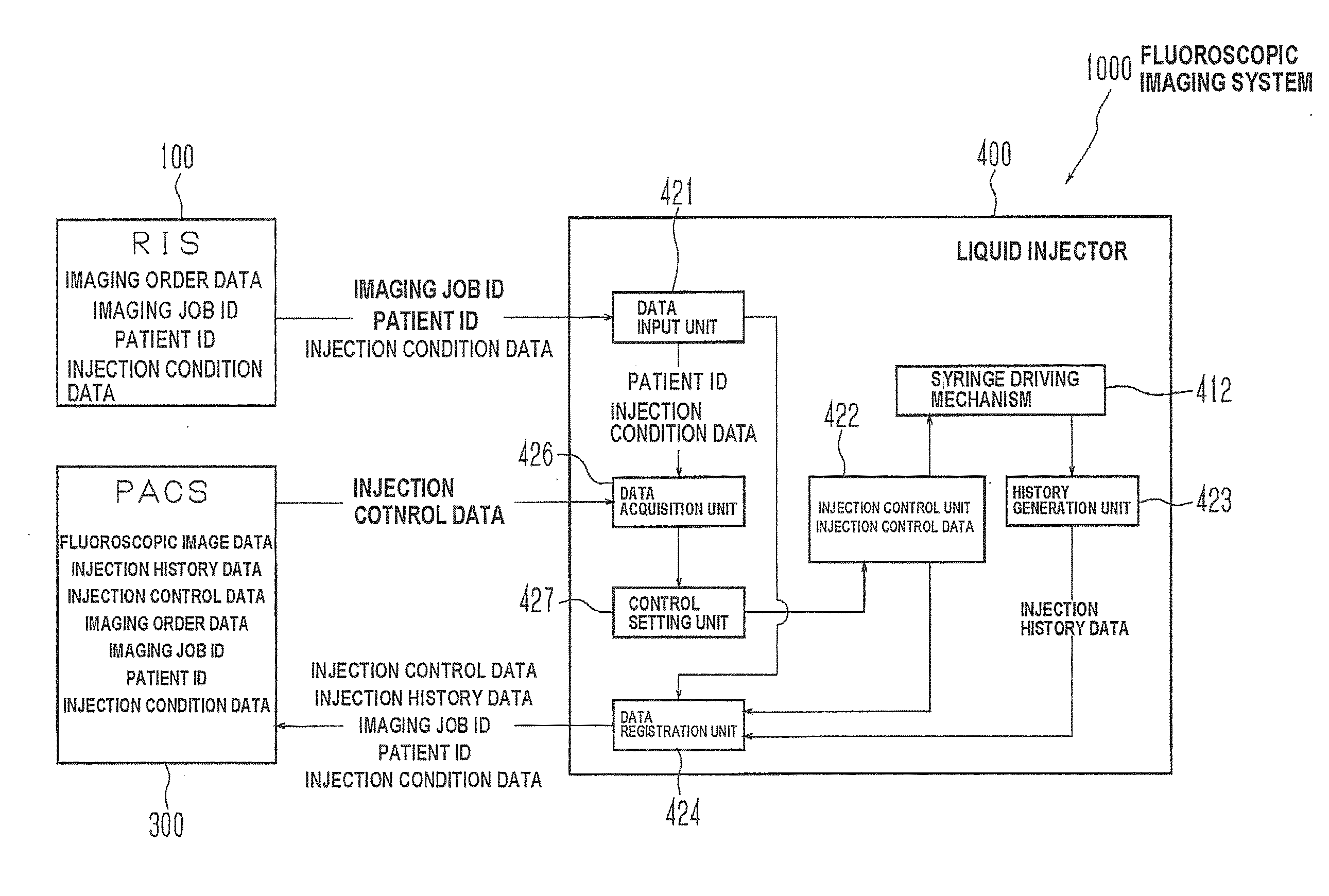
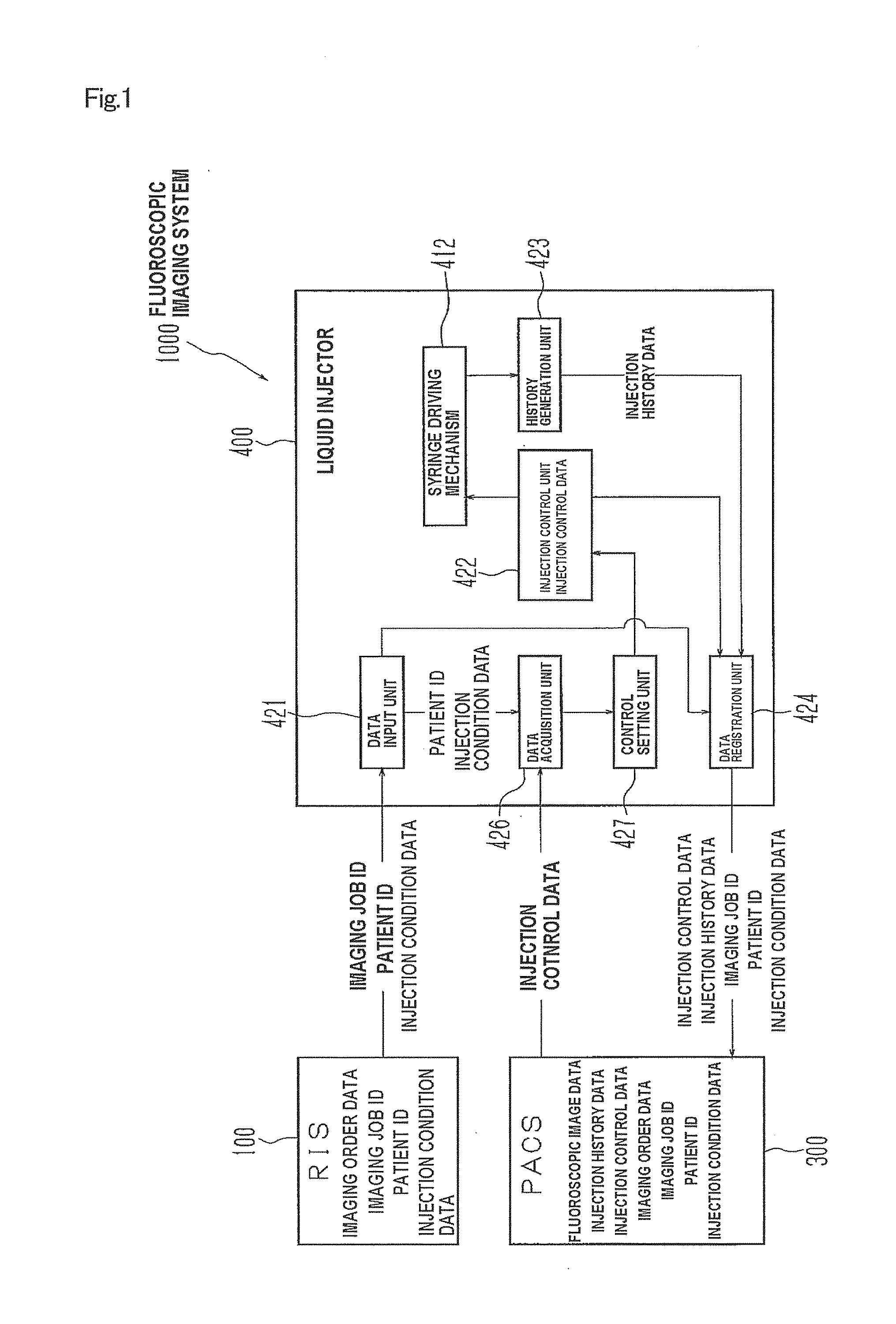
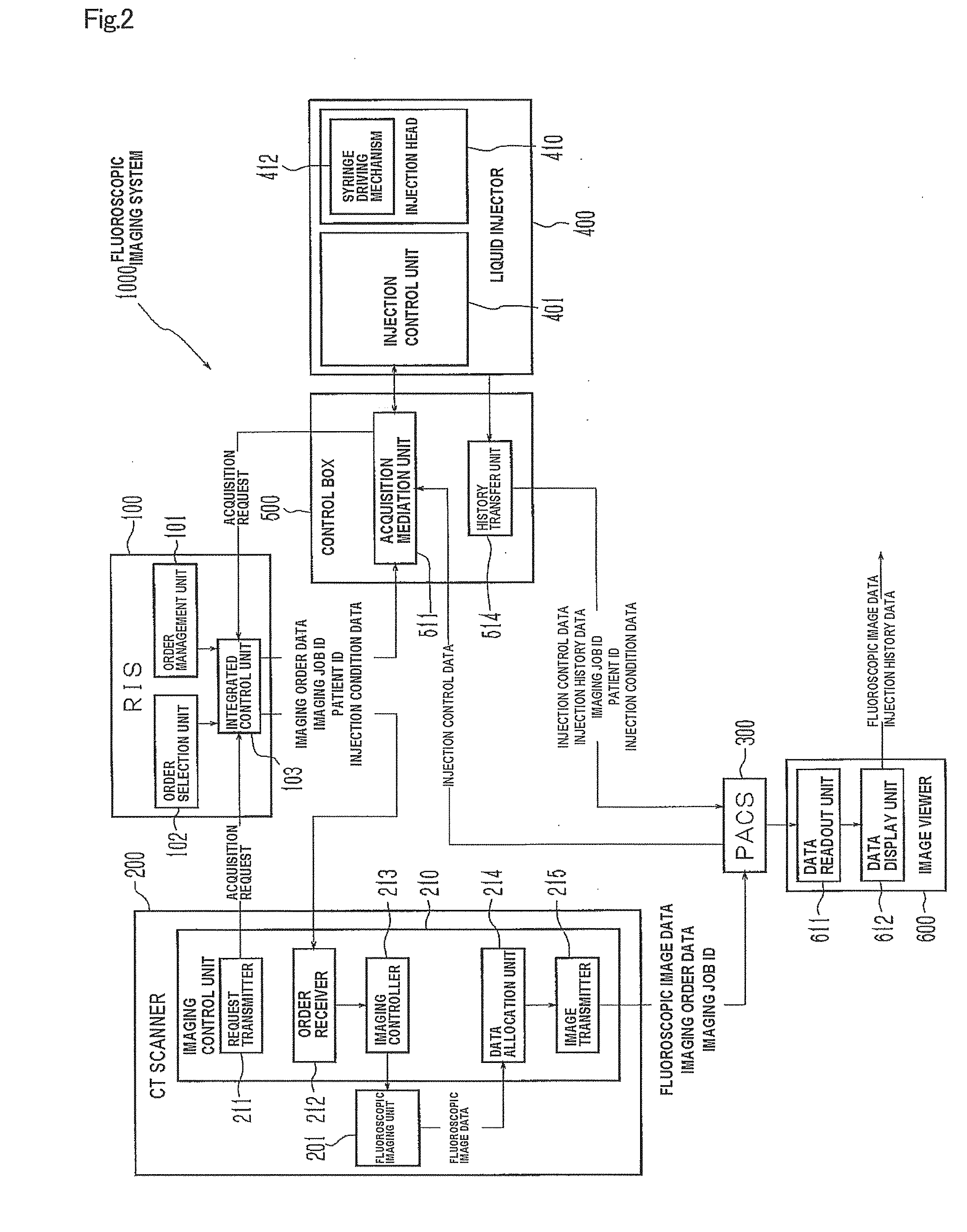
[0067]Hereunder, an embodiment of the present invention will be described referring to the drawings. A fluoroscopic imaging system 1000 according to the embodiment of the present invention includes, as shown in FIGS. 2 and 3, a RIS 100 which serves as an imaging management unit, a CT scanner 200 which serves as an imaging diagnostic apparatus, a PACS 300 which serves as a data storage unit, a liquid injector 400, a control box 500 which serves as a data control unit, and an image viewer 600.

[0068]In the fluoroscopic imaging system 1000 according to this embodiment, the CT scanner 200 is connected to the RIS 100 and the PACS 300, through communication networks 701, 702 such as a Local Area Network (LAN), as illustrated.

[0069]The control box 500 is also connected to the RIS 100, the PACS 300, and the liquid injector 400 through communication networks 703 to 705. To the PACS 300, the image viewer 600 is connected through the communication network 706.

[0070]The fluoroscopic imaging syst...


PUM


Abstract

Once a patient ID and injection control data are input to a liquid injector and liquid injection is executed, the injection control data and injection history data are registered with the patient ID in a PACS. When the same patient is to undergo the second or subsequent liquid injection, the previous injection control data and injection history data are acquired by inputting the patient ID, and set as renewed injection control data. Such arrangement eliminates the need to input the same injection control data for the patient. Further, since the injection control data of each patient is registered and acquired utilizing the patient ID as index, erroneous setting of inappropriate injection control data can be automatically prevented, when the patient undergoes the injection. The liquid injector allows, therefore, easily setting the injection control data, and yet prevents liquid injection based on inappropriate injection control data.

Description

TECHNICAL FIELD[0001]The present invention relates to a liquid injector that injects a medical liquid to a patient from whom fluoroscopic image data is to be taken, a fluoroscopic imaging system incorporated with the liquid injector, and a computer program for the liquid injector.BACKGROUND ART[0002]Imaging diagnostic apparatuses currently available for picking up a tomographic image, which is fluoroscopic image data of a patient, include a Computed Tomography (CT) scanner, a Magnetic Resonance Imaging (MRI) equipment, a Positron Emission Tomography (PET) equipment, and an ultrasonic diagnostic equipment. Also, medical equipments that pick up a vascular image, which is another fluoroscopic image data of the patient, include a CT angiographic equipment, a Magnetic Resonance Angiographic (MRA) equipment, and so forth.[0003]When one of such equipments is used, the patient often undergoes an injection of a medical liquid, also called a medical fluid, or simply liquid as the case may be,...

Claims


Application Information

Patent Timeline
Patent Type & Authority Applications(United States)
IPC IPC(8): A61B6/00G06Q10/00G06Q50/00G16H20/17G16H30/20
CPCA61M5/007A61M5/14546A61M2205/505A61B6/4494A61M2205/6054G06Q50/22A61M2205/60G16H30/20G16H20/17
Inventor NEMOTO, SHIGERU
Owner NEMOTO KYORINDO KK
Why Eureka
Try Eureka