Method and apparatus for a spray system

Active Publication Date: 2010-07-15
KUBACAK GREGORY JOHN CHARLES MR
View PDF28 Cites 14 Cited by
  • Summary
  • Abstract
  • Description
  • Claims
  • Application Information

AI Technical Summary

Benefits of technology

[0013]In accordance with the present invention, a right-of-way sprayer mounts the nozzles in a fixed and integral position on a common registration plate. The registration plate is monolithic, and is rigidly mounted to the spray head using support brackets. The registration plate may include a primary face and mounting tabs. The tabs can either be external to the primary face or cut out internally within the primary face of the registration plate depending on the application. The tabs may be coplanar with the primary face or can be angled or moved to create a desired swath coverage. Alternatively, the tabs may be reoriented to modify the spray pattern. With the nozzles rigidly mounted onto the plate, the entire plate is vibrated or nutated. The registration plate is rigid enough to maintain shape during a motion event, yet malleable enough to allow the tabs to be reoriented to adjust the spray pattern. The placement of the nozzles into the monolithic registration plate creates uniform motion among the nozzles. It is therefore an object of the present invention to mount the nozzles on the common registration plate, thereby preventing the nozzles from vibrating or nutating at levels that are not uniform.
[0014]Rigidly mounting the nozzles onto the monolithic registration plate provides the present invention with certain advantages. Having the nozzles rigidly mounted onto a common registration plate provides a more uniform nozzle motion and prevents nozzles from extending to undesired directions due to loosening of separate tabs during a motion event. Providing more uniform motion lessens the variability in droplet size, thereby producing a more accurate spray from the nozzles. Both of these measures aid in providing for more consistent swath coverage. More consistent swath coverage in the sprayer further provides the added benefit of reducing the cost of raw materials, such as herbicide, by enabling operators to more accurately predict an amount of herbicide required for a given application. Furthermore, having the ends of the nozzles securely mounted onto the single piece registration plate eliminates the possibility of the nozzles vibrating free, thereby cutting operating and maintenance costs due to machine failures.
[0015]Additional advantages include the relocation of solenoids closer to the registration plates, thereby reducing a residual flow system length to minimize the amount of fluid remaining within the residual flow system after shut-off. This feature, in combination with a reduced hose diameter, further reduces the amount of fluid remaining in the residual flow system, thereby reducing accidental drippage potential. The system further includes a reduced weight, approximately one-third of the predecessor, thereby allowing the spray head to vibrate or nutate at higher speeds with less damage due to friction on the bearings and motors of the spray head.
[0017]In a fourth embodiment, an improved spray unit is utilized in the vegetation engagement system disclosed in the third embodiment, and extensions thereof. The improvement includes a spray arm resistant to corrosion by chemicals, wherein the spray unit includes an electromagnetic field and an attractor secured to the spray arm, wherein the electromagnetic field forces the spray arm to move, thereby aiding droplet formation.

Problems solved by technology

However, in current right-of-way sprayers, the nozzles are not rigidly mounted on the spray head.
This lack of a rigid mounting system for the nozzles can cause several problems.
Illustratively, the lack of rigid mounting for the nozzles can create a disproportionate level of nutation in the nozzles.
The lack of uniformity in the level of nozzle nutation creates a varying level of droplet sizes among nozzles designed to nutate at the same rate, thereby affecting swath coverage and the saturation level of the herbicide.
Additionally, nutation of the spray head forces the elbows to rotate with respect to the manifolds, thereby moving the nozzles out of position.
In this situation, the chemical is applied unevenly, and the reoriented nozzle produces a spray pattern that lacks uniformity.
Also, as the ends of the nozzles are not rigidly attached to a rigid structure, the nozzles may point and direct spray to unintended locations producing undesirable swath coverage.
The lack of a rigid mounting system also increases the potential of causing nozzles to vibrate loose from their mounting points.
Still further, the remotely located solenoids create issues with residual product disposed within fluid circuits located beyond the flow control shut-offs.
The residual fluid remains in the pressurized hoses, and then seeps out of the system as the hoses contract due to the pressure loss.
The residual fluid may also drip out of the system during a change in the orientation of the system components, such as during a retraction, thereby delivering unintended drippage, possibly on desirable turf.
As such, a motion inducer is forced to work in a high working load range, thereby increasing the rate of motor and bearing failures.

Method used


Image

  • Method and apparatus for a spray system
  • Method and apparatus for a spray system
  • Method and apparatus for a spray system

Examples


first embodiment

[0057]A spray system 100, according to the present invention, includes a registration plate for positioning and restraining nozzles during a nutation event. The spray system 100 distributes and directs herbicide onto a roadside in a predetermined pattern through the use of a control system. The control system provides the capability to control the trajectory, nutation speed, as well as the flow of herbicide and herbicide components.

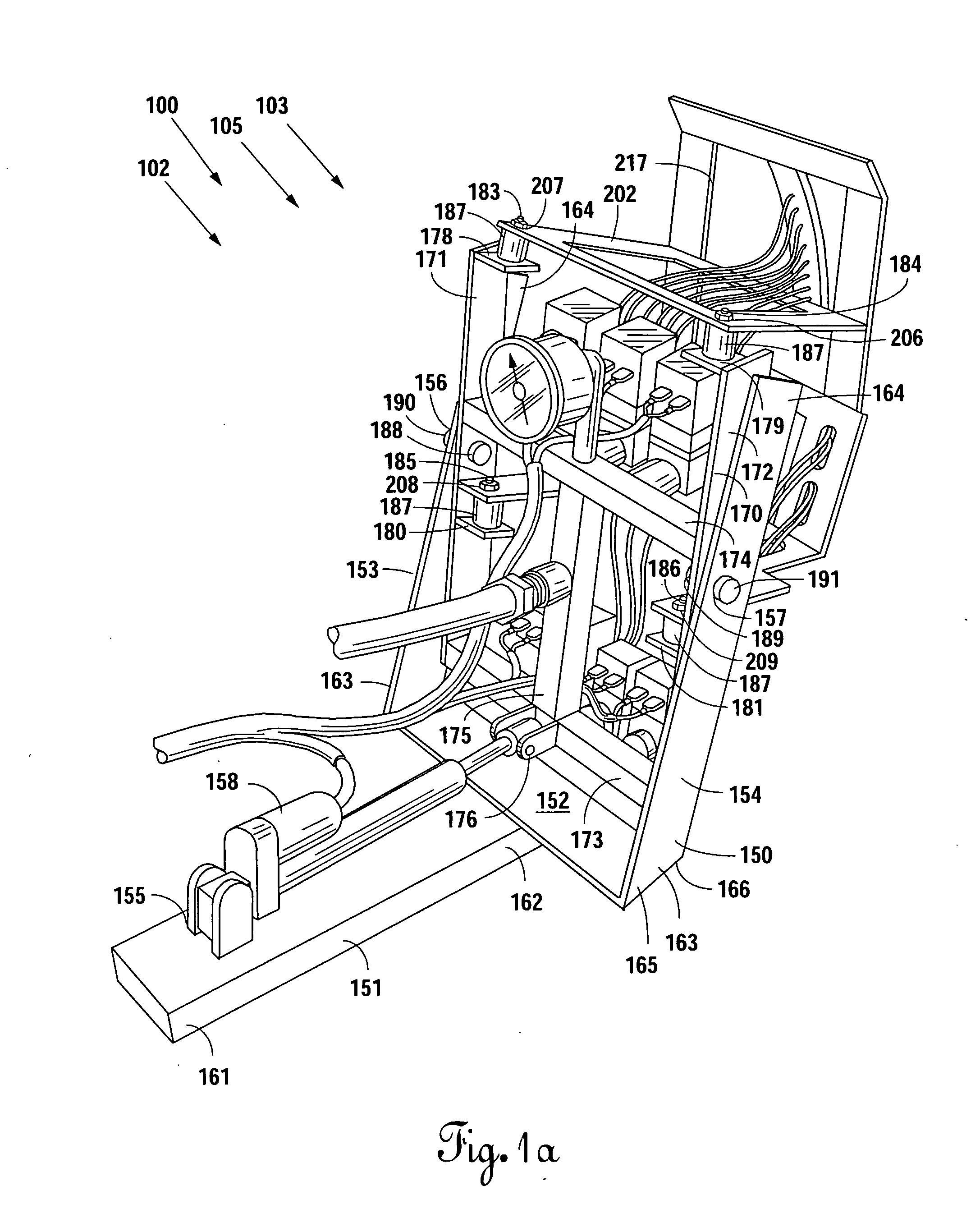
[0058]As shown in FIG. 1a, a spray system 100 includes a base frame 150, an inner frame 170, a spray head frame 202, a product circuit 102 a diluent circuit 103, and a control system 105. The outer frame 150 includes a base 151 having a first end 161 and a second end 162. The base 151 is of a steel plate construction, and is securable to virtually any form of structure. In this particular example, the base 151 is welded to a flat-bed of a pickup truck (not shown). However, one of ordinary skill in the art will recognize that the base 151 may be secured wi...

third embodiment

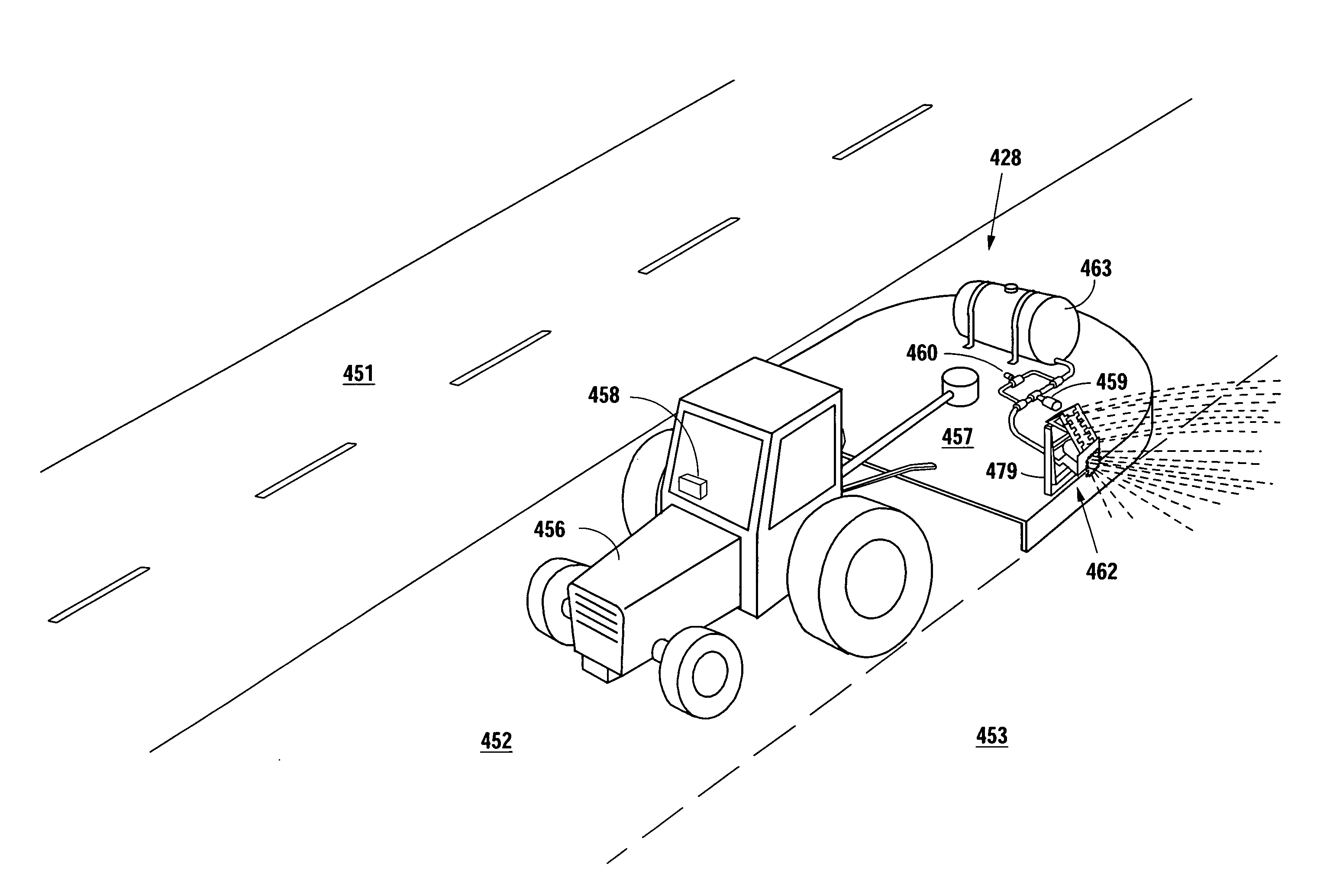
[0119]The spray system 450 includes a portable storage tank 463, a control system 455, at least one product circuit 464 including a pump 459, and a by-pass circuit 466 including a pressure regulator 460. The portable storage tank 463 is known in the art, and is located on the deck 454. The portable storage tank 463 may be refillable, replaceable, and is rigidly secured to the deck 454 to prevent the storage tank 463 from becoming separated from the vegetation engagement device 457. The portable storage tank 463 includes an inlet for filling, and an outlet for connection to the product circuit 464. The product circuit 464 extends from the outlet of the storage tank 463 to an inlet of the spray unit 463. The pump 459 may be any form of pump known in the art, such as centrifuigal, roller, piston, diaphragm, and the like, provided the operating pressure ranges of the system are within the designed pressure ranges of the pump, and the liquids being pumped are compatible with the material...

fourth embodiment

[0141]In this fourth embodiment, a vegetation engagement system 600 includes a service vehicle 456, as described in the previous embodiments, wherein the service vehicle 456 includes a vegetation engagement device 557 to engage vegetation in a first treatment zone and a spray system 650 that delivers at least one fluid in at least one swath to a second treatment zone. In the example illustrated, the vegetation engagement device 557 is a rotary mower that cuts vegetation as the vegetation engagement device 557 passes over the vegetation.

[0142]The spray system 650 is similar to the spray systems of the previous embodiments, wherein the spray system stores a product or products, pressurizes the product or products, and delivers the product or products in a controlled fashion through flow control units disposed in a spray unit, thereby delivering the fluid through the flow control units when the flow control units are in an open position, and ceasing the flow of the fluid when the flow ...


PUM


Abstract

An improvement to a roadside sprayer fixates spray nozzles on a registration plate. The registration plate may include integral tabs depending on the application. Inclination of the tabs is adjustable to place streams and droplets in a desired swath coverage. With the nozzles rigidly mounted onto the plate, the entire plate is nutated. The use of the registration plate in a spray unit creates a uniform nutation among the nozzles, thereby reducing variability in droplet placement, and providing a more predictable spray from the nozzles. In other embodiments, the spray unit is utilized in a spray system adaptable to service vehicles, and may be utilized in conjunction with a vegetation engagement device, such as a cutter to engage multiple zones of a roadway right-of-way. Additionally, an improved spray unit includes an electromagnetic field and an attractor to generate plate motion.

Description

BACKGROUND OF THE INVENTION[0001]1. Field of the Invention[0002]The present invention relates to a spray apparatus and more particularly to an automated apparatus for spraying herbicides on roadsides and other right-of-ways. The sprayer is mounted to a vehicle and is controlled by the operator of the vehicle.[0003]2. Description of the Related Art[0004]A right-of-way sprayer typically includes a tank for storing the herbicide and a dilution source, normally water, also stored in a tank. The herbicide and dilution sources are connected to a water pump where a mix occurs. The mix is then fed into a manifold controlled by solenoids that allow the operator to direct the flow of the mix. After traveling through the manifold, the mixture is fed through a series of hoses to individual nozzles, which mount on the ends of the plastic hoses. The nozzles are then mounted on a common platform called a spray head. The spray head can be nutated by any suitable means such as an electric vibrator t...

Claims


Application Information

Patent Timeline
IPC IPC(8): B05B15/08B05B1/00B05B5/00B05B15/68
CPCA01M7/006A01M21/043B05B1/14A01M7/0082B05B15/08B05B17/0607B05B15/061B05B15/62B05B15/68E01H11/00A01M7/005B05B17/0646
Inventor KUBACAK, JOHNNY LEE
Owner KUBACAK GREGORY JOHN CHARLES MR
Why Eureka
Try Eureka