Method for Increasing Turndown Capability in an Electric Power Generation System

a technology of power generation system and turndown capability, applied in the direction of electric generator control, machines/engines, mechanical equipment, etc., can solve the problems of low operating efficiency, limited range of low power commercial operation, and low power demand operation during periods of low power demand

Inactive Publication Date: 2010-07-15
SIEMENS ENERGY INC
View PDF9 Cites 38 Cited by
  • Summary
  • Abstract
  • Description
  • Claims
  • Application Information

AI Technical Summary

Problems solved by technology

However, operation during periods of low power demand has several drawbacks.
Minimizing fuel consumption by operating gas turbine units at lower power output levels results in lower operating efficiencies, even to the extent that the plant may operate at a loss.
Thus it has been a challenge to suitably turn down gas turbine power while complying with exhaust emissions requirements.
In the past, with this approach the achievable range of low power commercial operation has been quite limited.
This is because the extent to which the inlet guide vanes can be used to throttle down the air flow while sustaining necessary flame temperatures is limited.
Consequently, due to limitations in operating range of the inlet guide vanes, there has been a limited range of reduced output power relative to the maximum rated load while also avoiding unacceptably high emissions levels.

Method used


Image

  • Method for Increasing Turndown Capability in an Electric Power Generation System
  • Method for Increasing Turndown Capability in an Electric Power Generation System
  • Method for Increasing Turndown Capability in an Electric Power Generation System

Examples


Embodiment Construction

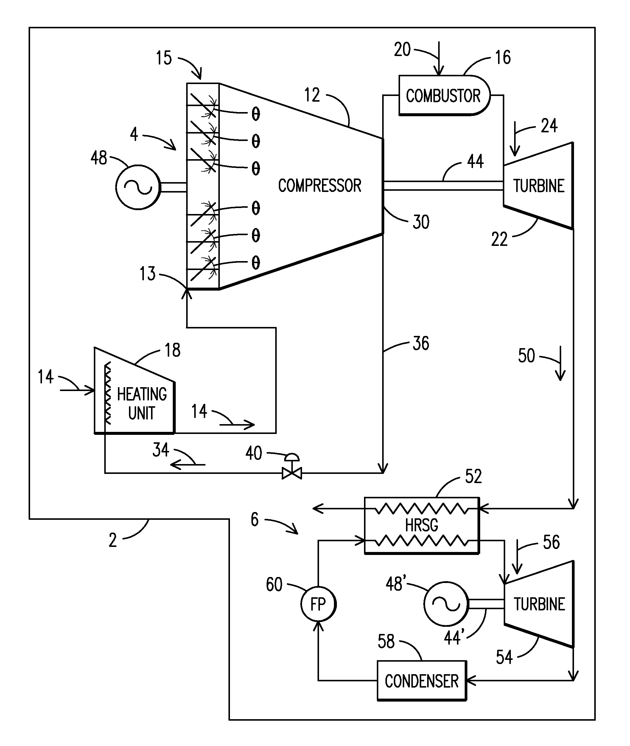
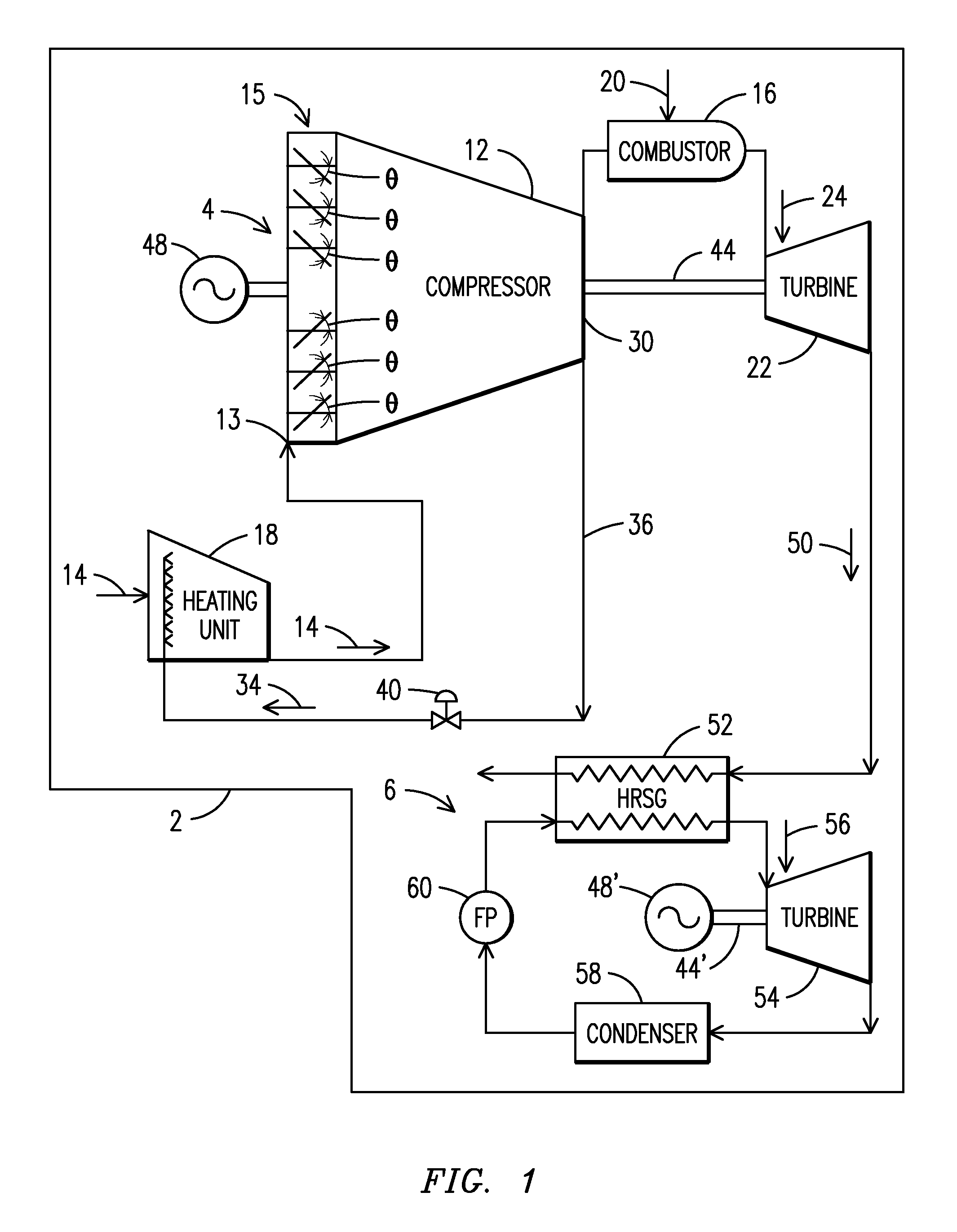
[0014]With reference to FIG. 1, there is shown in simplified schematic form a combined cycle electric power generation system 2 comprising a Brayton cycle 4 and a Rankine cycle 6. According to an embodiment of the invention, the Brayton cycle 4 includes a compressor 12 having an inlet port 13 which receives ambient air 14 that flows through a set of inlet guide vanes 15 for pressurization followed by discharge into a combustor 16. The air 14 is preheated by a heating unit 18 prior to intake by the compressor 12. Fuel 20 is also fed into the combustor 16 for reaction with the air 14. A set of adjustable inlet guide vanes 15 controls the amount of air flow entering the compressor 12. A power converting gas turbine 22 receives the hot gaseous exhaust gases 24 from the reaction of the air 14 and fuel 20 in the combustor 16. The hot exhaust gases 24 expand in the gas turbine 22 until they reach ambient pressure in a conventional manner.

[0015]An air extraction port 30 is located between t...


PUM


Abstract

A method of operating an electric power generation system (2). In one embodiment, a combustion chamber receives a combination of pressurized air (14) flow output from a compressor (12) and fuel (20) for combustion therein. The system (2) is operated at a relatively high steady state level of power output and then power is turned down by extracting a portion (34) of the pressurized air (14) flow before entry into the combustor (16). The method may further include throttling of air (14) flowing through the compressor (12) with inlet guide vanes (15). Features of the reduction in power include maintaining a characteristic combustor (16) minimum flame temperature with a volumetric percentage of NOx or CO emissions not exceeding those corresponding to the relatively high steady state operation.

Description

RELATED APPLICATION[0001]This application claims priority to provisional patent application U.S. 61 / 143,905 filed 12 Jan. 2009 which is incorporated herein by reference in the entirety.FIELD OF THE INVENTION[0002]The present invention relates generally to power systems and, more particularly, to power generation systems of the type incorporating gas turbines. More specifically, the invention relates to systems and methods for improving the operation of power plants during periods of low power demand.BACKGROUND OF THE INVENTION[0003]Gas turbines are used in a variety of power system configurations for power generation depending on the size, nature and variability of power demands. Simple cycle power plants utilizing a gas turbine and a generator offer relatively low life cycle costs, but relatively low efficiencies on the order of forty percent. Commonly, gas turbine designs provide outputs ranging from five to 50 megawatts and much larger turbine outputs range in the hundreds of meg...

Claims


Application Information

Patent Timeline
Patent Type & Authority Applications(United States)
IPC IPC(8): F02C9/18F02C6/00
CPCF02C3/10F02C3/365F02C6/08F05D2250/51F02C9/20Y02E20/16F02C6/18
Inventor PLANT, ADAM D.OLIVERI, CHRISTOPHER R.CARPENTER, BRUCE H.TEEHAN, DAMIEN G.ELWOOD, DAVID D.
Owner SIEMENS ENERGY INC
Why Eureka
Try Eureka