Valve opening/closing timing control apparatus

a timing control and valve opening/closing technology, applied in the direction of output power, machines/engines, couplings, etc., to achieve the effect of reliable retarding control

Active Publication Date: 2010-07-15
AISIN SEIKI KK
View PDF11 Cites 17 Cited by
  • Summary
  • Abstract
  • Description
  • Claims
  • Application Information

AI Technical Summary

Benefits of technology

[0022]If a second pump that can act, when needed, as a substitute for the first pump is provided as described above, it is possible for the second pump to compensate for any shortage in pressure which occurs in the work fluid provided by the first pump in association with engine stop. Therefore, unlike the conventional apparatus disclosed in Patent Document 1 described above, there is no need to set the urging force of the urging mechanism to override the displacing force in the retarding direction by the minimal-pressure work fluid provided by the first pump. With this arrangement, the returning from the retarding phase region to the intermediate restricting phase can take place in a speedy manner. Further, preferably, in order to realize more reliable retarding control, the second pump is activated if the relative phase is to be displaced in the retarding direction beyond said intermediate restricting phase when the work fluid fed by the first pump is at the minimal pressure.
[0023]According to a still ...

Problems solved by technology

However, if the cam reaction force, and the force resulting from e.g. viscosity of oil, effective in the retarding direction, are weak, the displacement from th...

Method used


Image

  • Valve opening/closing timing control apparatus
  • Valve opening/closing timing control apparatus
  • Valve opening/closing timing control apparatus

Examples


Embodiment Construction

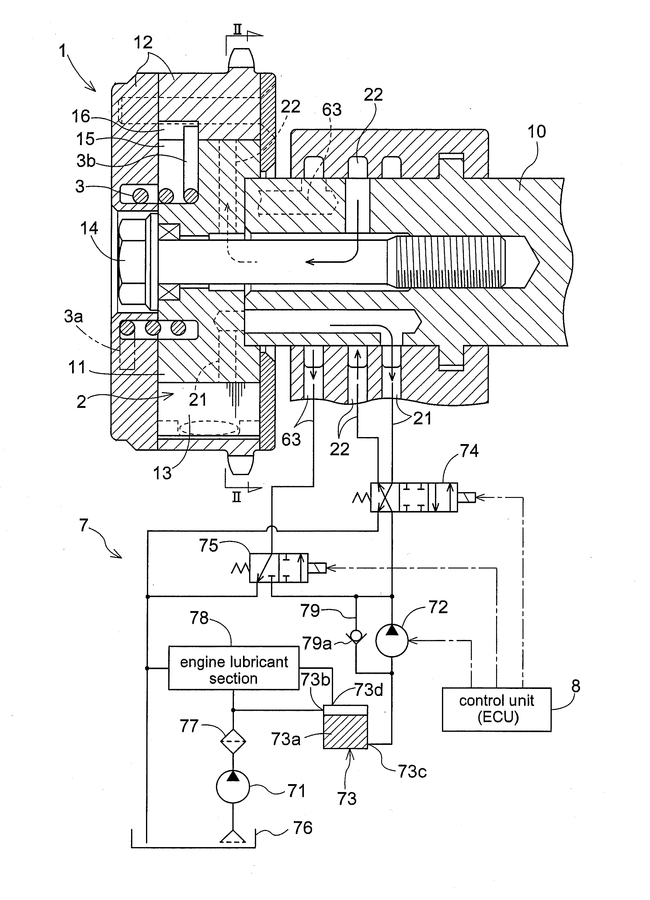
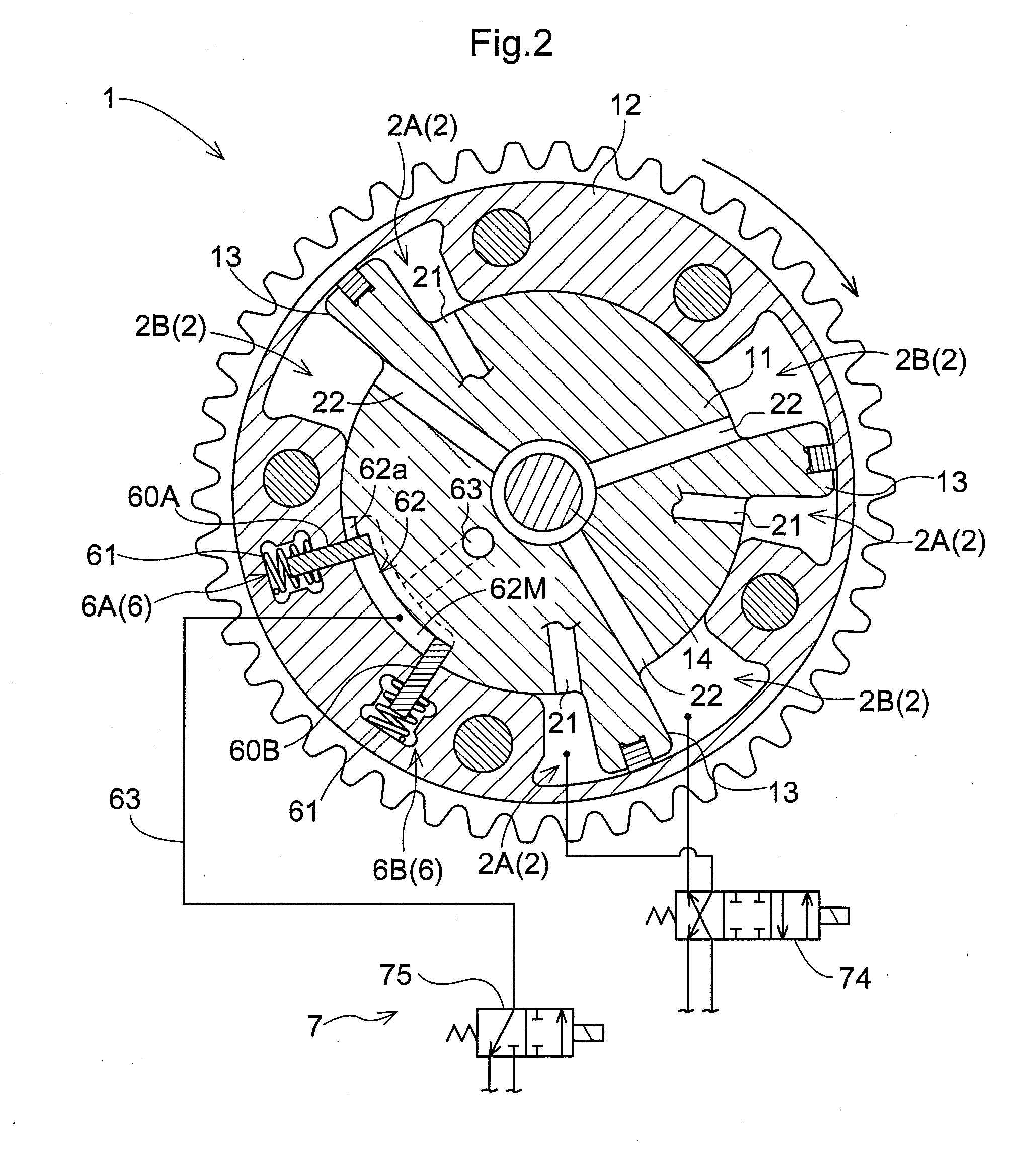
[0034]Next, one embodiment of the present invention will be described with reference to the accompanying drawings. FIG. 1 is a section view schematically showing the construction of a valve opening / closing timing control apparatus according to the present invention. FIG. 2 is a section view taken along a line II-II in FIG. 1, as a plane view schematically showing a condition of a phase displacing mechanism under one operational state. Numeral 1 in the figures denotes the phase displacing mechanism. This phase displacing mechanism 1 includes a drive-side rotational member 12 rotatable in synchronism with an internal combustion engine (“engine”) and a driven-side rotational member 11 arranged coaxially with the drive-side rotational member 12. In the instant embodiment, there is illustrated an exemplary arrangement of the driven-side rotational member 11 being disposed on the inner side of the drive-side rotational member 12. And, the drive-side rotational member 12 is provided in the...


PUM


Abstract

A valve opening/closing timing control apparatus includes a phase displacing mechanism for displacing relative phase between a drive-side rotational member and a driven-side rotational member rotatable in unison with a cam shaft, a locking mechanism capable of locking the relative phase to an intermediate locking phase suitable for starting and releasing this lock by a work fluid when needed and an urging mechanism configured to provide an urging function for urging the phase displacing mechanism toward an advancing side in a restricted range between an intermediate restricting phase located more on the retarding side than the intermediate locking phase and a most retarding phase.

Description

TECHNICAL FIELD[0001]The present invention relates to a valve opening / closing timing control apparatus for controlling opening / closing timing of at least one of an intake valve and an exhaust valve of an internal combustion engine.BACKGROUND ART[0002]The convention has implemented a valve timing control apparatus for changing opening / closing timing of an intake valve and / or an exhaust valve according to an operational condition of an internal combustion engine (“engine”). For instance, there is known a mechanism for changing the opening / closing timing of the intake valve which is opened / closed in association with rotation of a cam shaft, by changing a rotational phase of the cam shaft relative to a crank shaft. Incidentally, the intake valve and the exhaust valve each has its own timing favorable for starting the engine. And, this opening / closing timing often differs from the opening / closing timing of the same valve during traveling of the vehicle. More particularly, the rotational ...

Claims


Application Information

Patent Timeline
IPC IPC(8): F01L1/34
CPCF01L1/022F01L1/024F01L1/3442F01L2001/34426F01L2001/34446F01L2001/34463Y02T10/18F01L2001/34473F01L2001/34479F01L2001/34483F01L2800/01F01L2800/03F02D13/0215F01L2001/34466Y02T10/12
Inventor SUZUKI, SHIGEMITSUTOMA, NAOTOKANADA, YOJIMUKAIDE, HIROKI
Owner AISIN SEIKI KK
Why Eureka
Try Eureka