
Liquid Filtration Using Pressure Difference Across a Hydrophobic Membrane

a hydrophobic membrane and liquid filtration technology, applied in the direction of membranes, distillation, separation processes, etc., can solve the problems of many diseases and deaths, the availability of fresh water is a problem in many regions of the world, and the problem of worsening the problem of fresh water availability

Inactive Publication Date: 2010-07-15
MASSACHUSETTS INST OF TECH
View PDF28 Cites 15 Cited by
  • Summary
  • Abstract
  • Description
  • Claims
  • Application Information

AI Technical Summary

Benefits of technology

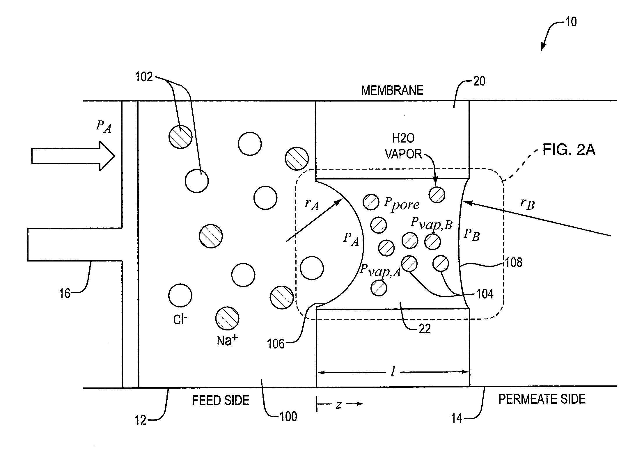
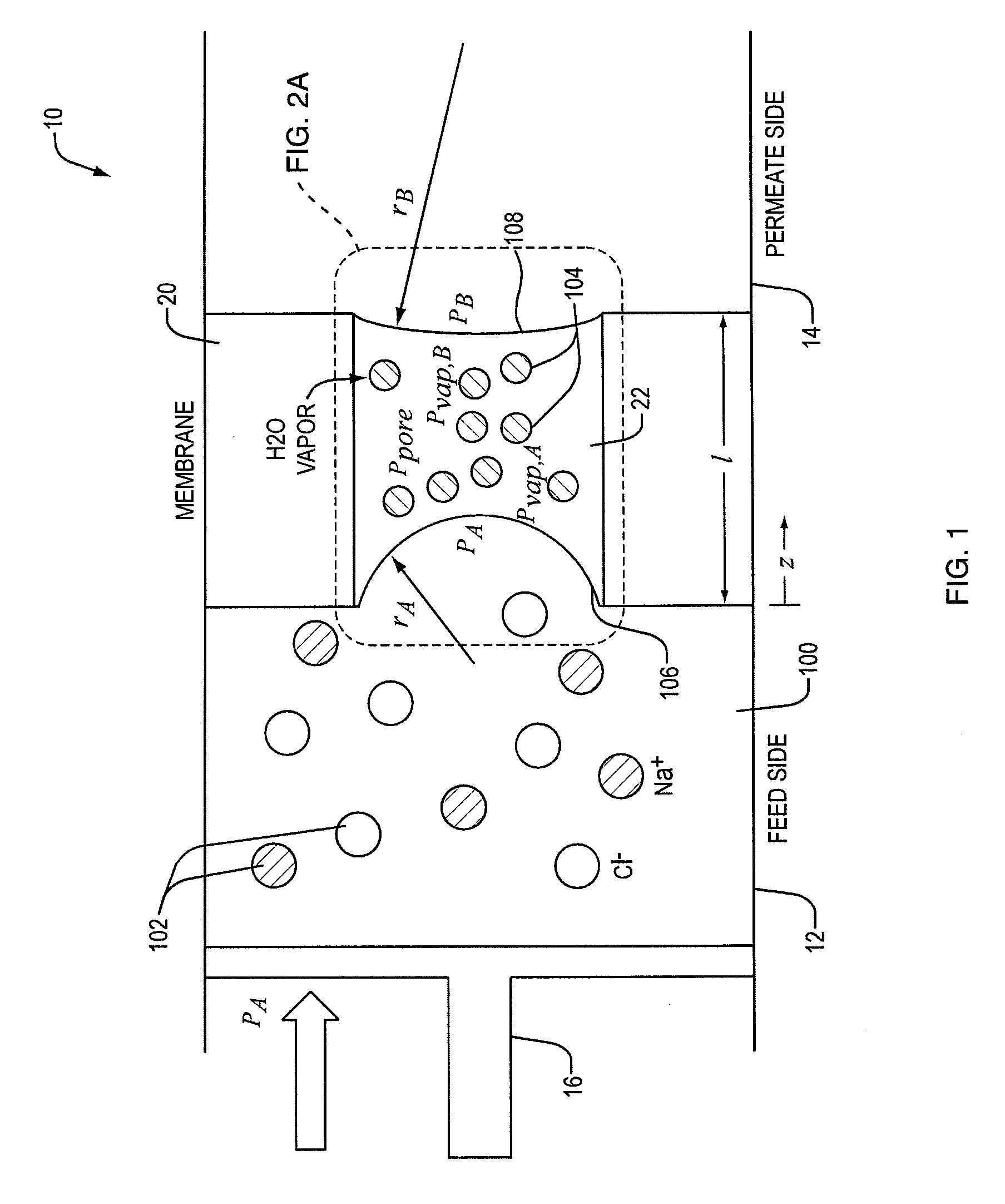
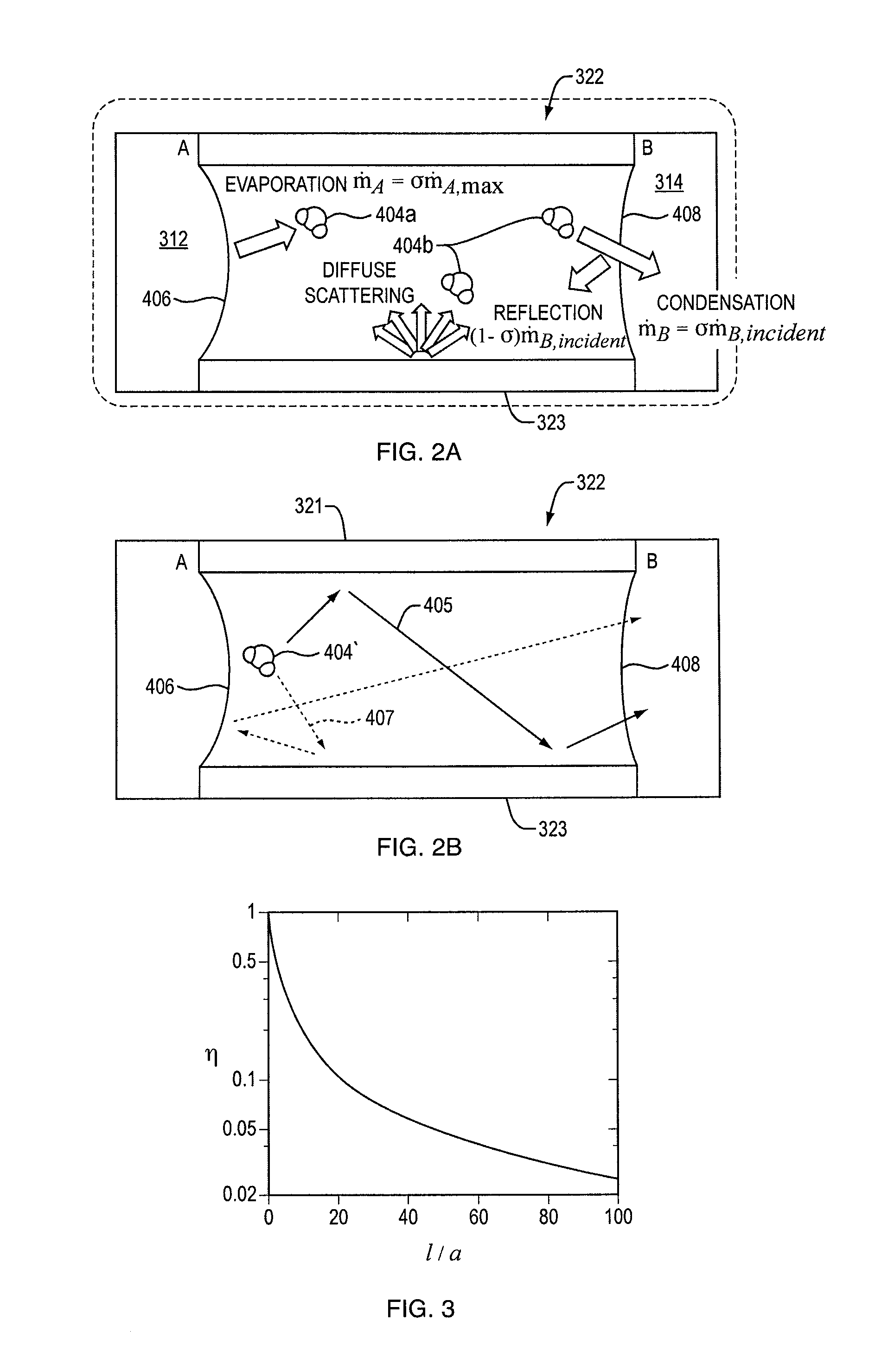
[0013]In another embodiment of a method for filtering a liquid substance includes providing a porous membrane disposed between a feed side and a permeate side, providing a liquid substance on the feed side, forming a first liquid meniscus at one side of a pore of the porous membrane, forming a second liquid meniscus at another side of the pore of the porous membrane, and transporting the substance as a vapor between the first and second menisci. The method can further include increasing a curvature of one or both of the first and second menisci. The method can also be approximately isothermal. In one embodiment, the method further includes providing a second porous membrane disposed between the feed side and the permeate side, providing a gap between the feed side and the permeate side such that the first porous membrane is disposed on one side of the gap, adjacent to the feed side, and the second porous membrane is disposed on another side of the gap, adjacent to the permeate side. In such an embodiment, the first liquid meniscus is formed at a pore of the first porous membrane adjacent to the gap and the second liquid meniscus is formed at a pore of the second porous membrane adjacent to the gap. The method can further include degassing the gap.

Problems solved by technology

Although water is one of the most abundant resources in nature, the availability of fresh water is a problem in many regions of the world.
Increasing demand and changing climate may worsen the fresh water availability problem.
In developing countries, many diseases and deaths are attributed to the poor quality of water.
The scarcity of fresh water is expected to become more serious in those countries, and also in the Middle East and North African countries that are suffering from lack of renewable fresh water.
This water shortage problem has necessitated a variety of desalination technologies and methods for brackish water and sea water.
While these methods have been used and improved upon for a number of years, they still have many deficiencies that can be improved.
These deficiencies include the relatively high energy requirements, high cost, fouling issues, pre-treatment requirements, and the low flux which many of the current, membrane-based devices and methods experience.
The main disadvantage of this approach, however, comes from the high energy requirement due to the high latent heat of water, which can be approximately 290 kJ / kg to desalinate sea water in some instances.
While membrane-based reverse osmosis is more economical than the thermal processes with respect to the cost of energy, it too involves its own challenges.
For instance, a large fraction of the cost for desalination arises from membranes and their maintenance.
Further, although increasing the membrane flux may decrease the required membrane area and capital costs, it requires large pressures that lead to viscous losses and decreased efficiency.
The cost of producing current membrane-based reverse osmosis systems increases as the concentration of the solute increases.
Still further, reverse osmosis membranes suffer from fouling, scaling, viscous losses, having weak resistance to chlorine, having insufficient boron rejection, and having low mass flux per unit area of the membrane, which in turns requires large membrane areas.
Direct contact membrane distillation is highly inefficient as there is a huge heat loss across the membrane by conduction, and other distillation approaches have to deal with heat transport from the condensate to the evaporating salt water.
Other variations of membrane distillation, such as air-gap membrane distillation and vacuum-enhanced membrane distillation, also suffer from similar drawbacks.

Method used


Image

  • Liquid Filtration Using Pressure Difference Across a Hydrophobic Membrane
  • Liquid Filtration Using Pressure Difference Across a Hydrophobic Membrane
  • Liquid Filtration Using Pressure Difference Across a Hydrophobic Membrane

Examples


Embodiment Construction

[0040]Certain exemplary embodiments will now be described to provide an overall understanding of the principles of the structure, function, manufacture, and use of the devices and methods disclosed herein. One or more examples of these embodiments are illustrated in the accompanying drawings. Those skilled in the art will understand that the devices and methods specifically described herein and illustrated in the accompanying drawings are non-limiting exemplary embodiments and that the scope of the present invention is defined solely by the claims. The features illustrated or described in connection with one exemplary embodiment may be combined with the features of other embodiments. Such modifications and variations are intended to be included within the scope of the present invention.

[0041]Devices and methods are generally provided that rely on pressure differences to filter a liquid. In fact, no temperature difference is required across the water-water vapor interfaces that can b...


PUM


Abstract

Method and devices for filtering liquid are provided that rely on pressure difference to filter liquid. In one embodiment, a device for filtering liquid includes a feed chamber, a permeate chamber, and a porous membrane that is at least partially hydrophobic and has one or more pores configured to be permeable to vapor. A pressure of a liquid substance in the feed chamber is increased such that vapor of the liquid substance is transported from the feed chamber to the permeate chamber. The resistance of flow in a hydrophilic layer of the membrane can be controlled to make the membrane defect-tolerant. In another embodiment, a second porous membrane is further included and the second porous membrane is spaced apart from the first porous membrane. Various methods for filtering liquid are also provided.

Description

PRIORITY[0001]The present invention claims priority to U.S. Provisional Application No. 61 / 143,521, “Liquid Filtration Using Pressure Difference Across a Hydrophobic Membrane” and filed on Jan. 9, 2009.FIELD[0002]The present invention generally relates to devices and processes for filtering a liquid substance and more specifically relates to using a pressure difference to induce vapor phase transport of the substance across one or more hydrophobic membranes to filter the liquid.BACKGROUND[0003]Although water is one of the most abundant resources in nature, the availability of fresh water is a problem in many regions of the world. Increasing demand and changing climate may worsen the fresh water availability problem. In developing countries, many diseases and deaths are attributed to the poor quality of water. The scarcity of fresh water is expected to become more serious in those countries, and also in the Middle East and North African countries that are suffering from lack of renew...

Claims


Application Information

Patent Timeline
IPC IPC(8): B01D61/36B01D69/10B01D69/12
CPCB01D61/364B01D65/102B01D2325/08B01D2325/38C02F2103/08C02F1/441C02F1/444C02F1/445C02F1/448C02F1/44Y02A20/131
Inventor KARNIK, ROHIT N.LEE, JONGHO
Owner MASSACHUSETTS INST OF TECH
Learn More