Self-supporting bench assembly for personnel transport

Inactive Publication Date: 2010-07-15
MICHELI JOHN
View PDF24 Cites 5 Cited by
  • Summary
  • Abstract
  • Description
  • Claims
  • Application Information

AI Technical Summary

Benefits of technology

[0013]In yet another form of the invention, the bottom frame assembly, the plurality of leg assemblies, and the main supports for the back assembly are all made from the same type of material with universal fasteners so that repairs can be easily made and reducing the number of structural components, making the assembly less complicated and easy to repair. The members used to form the seating surface and the bulk of the back support assembly are likewise made from the same type of materials, preferably a pull-extruded fiber-reinforced polymer such as a fiber reinforced plastic wherein the fibers provide a ballistic characteristic to the material as well as making it strong and lightweight.
[0014]According to another form of the invention, th

Problems solved by technology

These configurations make such seating extremely uncomfortable when traveling over long distances and that often lead to lower back infections, neck, and kidney injury.
Moreover, the seating has not been removable for use off the vehicle during times of rest or when seating away from the vehicle is desired.
The prior art seating assemblies used in commercial or military personnel transport vehicles generally have the following unsatisfactory attributes.
Past seating configurations also only allow the seat to pivot downwardly supported by a truss member that can only secure the seat if it is supported by a fixed stop such as the side of the vehicle.
Other disadvantages of past and present seating configurations include ergonomic inefficiencies.
When filled to capacity, and the occupants side-by-side, excessive pressure is applied to a limited area of the body, producing back and neck injuries, trauma to the kidneys and digestiv

Method used


Image

  • Self-supporting bench assembly for personnel transport
  • Self-supporting bench assembly for personnel transport
  • Self-supporting bench assembly for personnel transport

Examples


Example

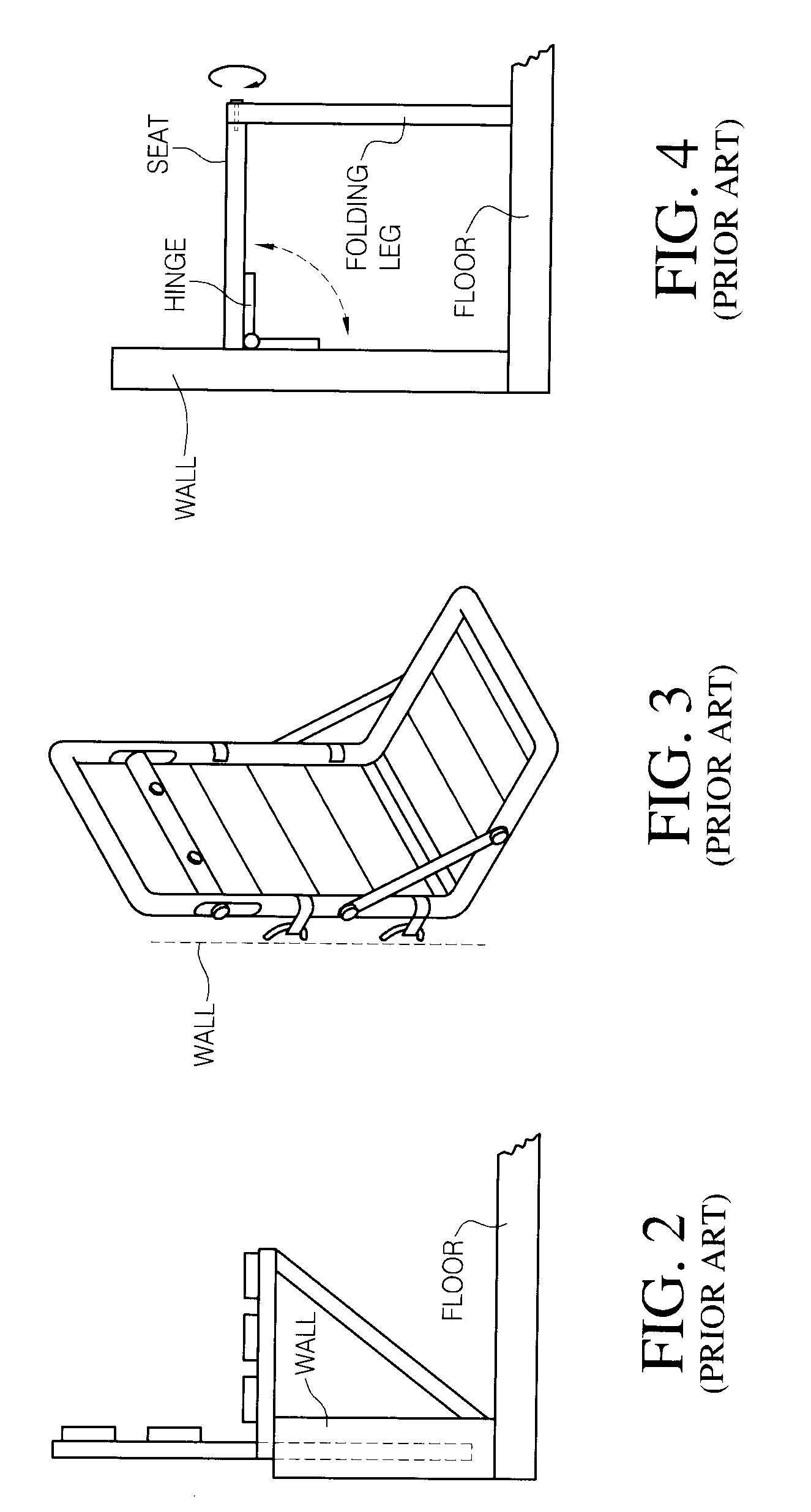
[0026]For purposes of description only, the terms “upper,”“lower,”“right,”“left,”“rear,”“front,”“vertical,”“horizontal,” and derivatives thereof shall relate to the invention as oriented in FIG. 2. However, it is to be understood that the invention may assume various alternative orientations and step sequences, except where expressly specified to the contrary. It is also to be understood that the specific devices and processes illustrated in the attached drawings and described in the following specification are simply exemplary embodiments of the inventive concepts defined in the appended claims. Specific dimensions and other physical characteristics relating to the embodiments disclosed herein are not to be considered as limiting, unless the claims expressly state otherwise.

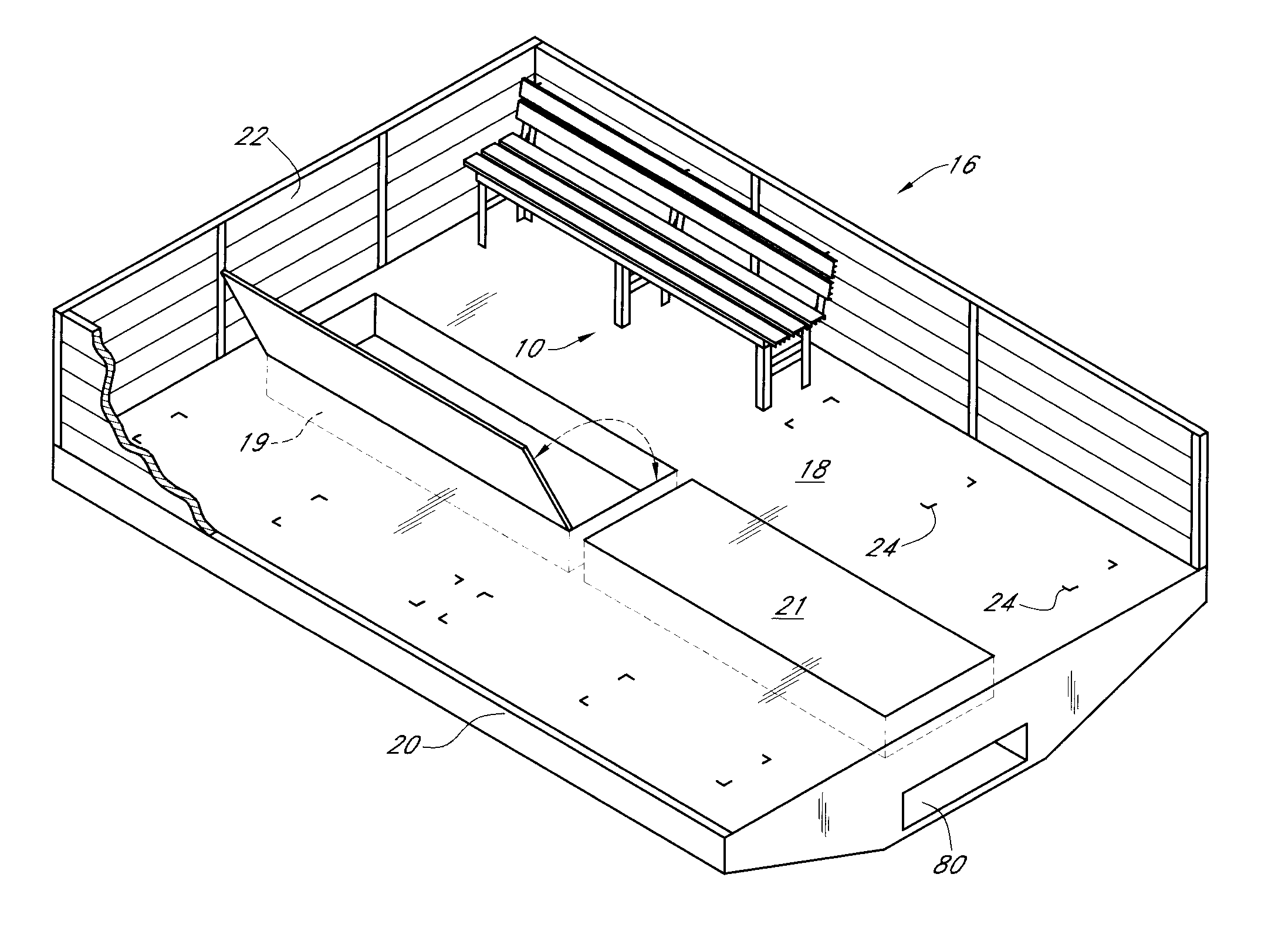
[0027]Prior bench designs for use in military transports often utilized a simple hinged bench attached to a back support such that the seat could fold up or down relative to the back. See FIGS. 2-3. Other versio...


PUM


Abstract

A seating system for a vehicle having a cargo bed including a bench assembly for providing seating for personnel. The bench assembly includes a bottom frame assembly having opposing longitudinal edges and a plurality of slats attached to the bottom frame assembly to provide a platform for the seat slats. A back assembly is provided extending from one of the longitudinal edges of the bench assembly. A bracket assembly interconnects the back assembly to the bottom frame assembly. The bracket assembly includes an elongated slot portion and a latch portion permitting the back assembly to translate relative to the bench assembly and pivot relative to the bracket assembly to keep the back assembly erect in a first position and to be disposed in a non-supporting or second position when not in use. A plurality of leg assemblies are attached to the bottom frame assembly in a manner that permits them to be extended in a first position and retracted into a nested position within the bottom frame assembly in a second position so that the entire seating assembly may be stowed in a compact manner.

Description

STATEMENT REGARDING FEDERALLY SPONSORED RESEARCH OR DEVELOPMENT[0001]This invention was not conceived or developed using any funding provided by the United States government, it agencies, or other governmental agency.BACKGROUND OF THE INVENTION[0002]1. Field of the Invention[0003]This invention relates to seating and cargo system for a vehicle. More specifically the invention relates to a self-supporting, foldable and stowable seating system for use in or out of a cargo bed of a transport vehicle, and particularly to a seating system for use by personnel in military or commercial transport vehicles.[0004]2. Description of the Related Art[0005]Historically many vehicles provided the dual purpose of transporting supplies and personnel such as troops and support personnel to and from the battlefield and other specified locations. Generally these vehicles include a large cargo bay or bed that was open and accessible for carrying containers. When needed to transport military personnel an...

Claims


Application Information

Patent Timeline
IPC IPC(8): B60N2/00
CPCB60N2/005B60N2/68B60N2/20
Inventor MICHELI, JOHN
Owner MICHELI JOHN
Why Eureka
Try Eureka