Method and Apparatus for Surgical Instrument Identification

a surgical instrument and identification method technology, applied in the field of surgical instrument identification methods and equipment, can solve the problems of limited information that the symbols can contain, damage to instruments, damage to items and some types of rubber, etc., and achieve the effect of reducing handling costs

Inactive Publication Date: 2010-07-15
WARSAW ORTHOPEDIC INC
View PDF57 Cites 19 Cited by
  • Summary
  • Abstract
  • Description
  • Claims
  • Application Information

AI Technical Summary

Benefits of technology

[0013]Thus, there is a need to provide an inventory system for medical, orthopedic and surgical instruments that is more efficient for reducing handling costs, automating the verification process of items such as orthopedic and surgical instruments, and to overcome the aforementioned shortcomings of conventional identification techniques.
[0014]Embodiments of the invention provide systems and methods for automatically and wirelessly inventorying orthopedic and surgical instruments and the like, by retrieving information from the instrument and performing one or more operations on the data, such as, storing the data, comparing it against previously stored data, and / or recording new data. The information preferably may include information indicative of the manufacturer, part number, serial number and manufacturing data, usage and maintenance history of each instrument, and the like. The inventive systems and methods allow for lower handling costs of surgical instruments, increase the accuracy of the verification process of data pertaining to each instrument with a reduction of human contact, and provide for real-time data collection resulting in fast data acquisition that speeds up the inventory updating of such instruments.
[0015]Embodiments of the invention also are capable of circumventing some of the problems associated with manual removal and scanning of surgical instruments by implementing radio frequency tagging of each instrument, and creating a database on a wireless reader in order to wirelessly compare and ascertain the history of each tagged instrument as it arrives in a distribution center. An RFID system preferably includes three components: (i) an antenna or coil; (ii) a transmitter / receiver (transceiver) with a decoder; and (iii) an RF tag that is the transponder (tran(smitter)+(re)sponder) that is electronically programmed with certain unique information. The antenna emits radio frequency waves to activate the transponder (tag) in order to read or write data to it. In turn, the tag transmits data back to the antenna, and the data can be used to interface with a database to carry out a function such as inventory processing. One advantage of using RFID is that it does not require direct contact or line-of-sight scanning.
[0016]A feature of an embodiment of the invention provides a system and method for automatically and wirelessly inventorying orthopedic surgical instruments and the like. The system and method preferably retrieves information from an RFID transponder tag attached or integral to the orthopedic and surgical instrument, such as information that is indicative of the manufacturer, part number, serial number, manufacturing data, usage, and maintenance history, and maintenance scheduling of each instrument. The system and method allows for lower handling costs of orthopedic and surgical instruments, increases the accuracy of verification process of data pertaining to each instrument with a reduction of human contact, and provides real-time data collection resulting in fast data acquisition, which ultimately speeds up inventory updating of such instruments.

Problems solved by technology

The amount of information that the symbols can contain is limited by the space constraints of the label.
Many plastic items and some types of rubber are damaged by repeated autoclaving, and prolonged immersion of the instruments in a sterilizing solution may damage the instruments.
Such a method typically requires that the instrument be removed from the tray on arrival and individually scanned by an operator, a method that is costly, and time-consuming.
There are some limitations to bar codes, however, that limit their application to surgical instruments and trays.
Bar codes are limited in size by resolution limitations of bar code scanners, and the amount of information that the symbols can contain is limited by the physical space constraints of the label.
Therefore, some objects may be unable to accommodate bar code labels because of their size and physical configuration.
Another limitation of bar code readers is that they require line of sight in order to read the reflection pattern from a bar code.
One problem is that as labels become worn or damaged, and they can no longer be read with the bar code scanner.
This is particularly likely in the field of surgical instrument trays because of the harsh conditions the labels must undergo during sterilization.
Also, because a person operating the bar code scanner must physically orient either the scanner or the product to achieve line of sight on each item being scanned, items must be scanned one at a time resulting in prolonged scan time.
In addition, because bar code scanning requires the operator to handle each instrument in order to scan it, a potential safety problem is created.
Soiled instruments pose a biohazard because they may have come in contact with bodily fluids, and often have sharp edges.
Therefore, direct human contact either pre or post sterilization may be problematic.
Another limitation of bar code labels is that they are static.

Method used


Image

  • Method and Apparatus for Surgical Instrument Identification
  • Method and Apparatus for Surgical Instrument Identification
  • Method and Apparatus for Surgical Instrument Identification

Examples


Embodiment Construction

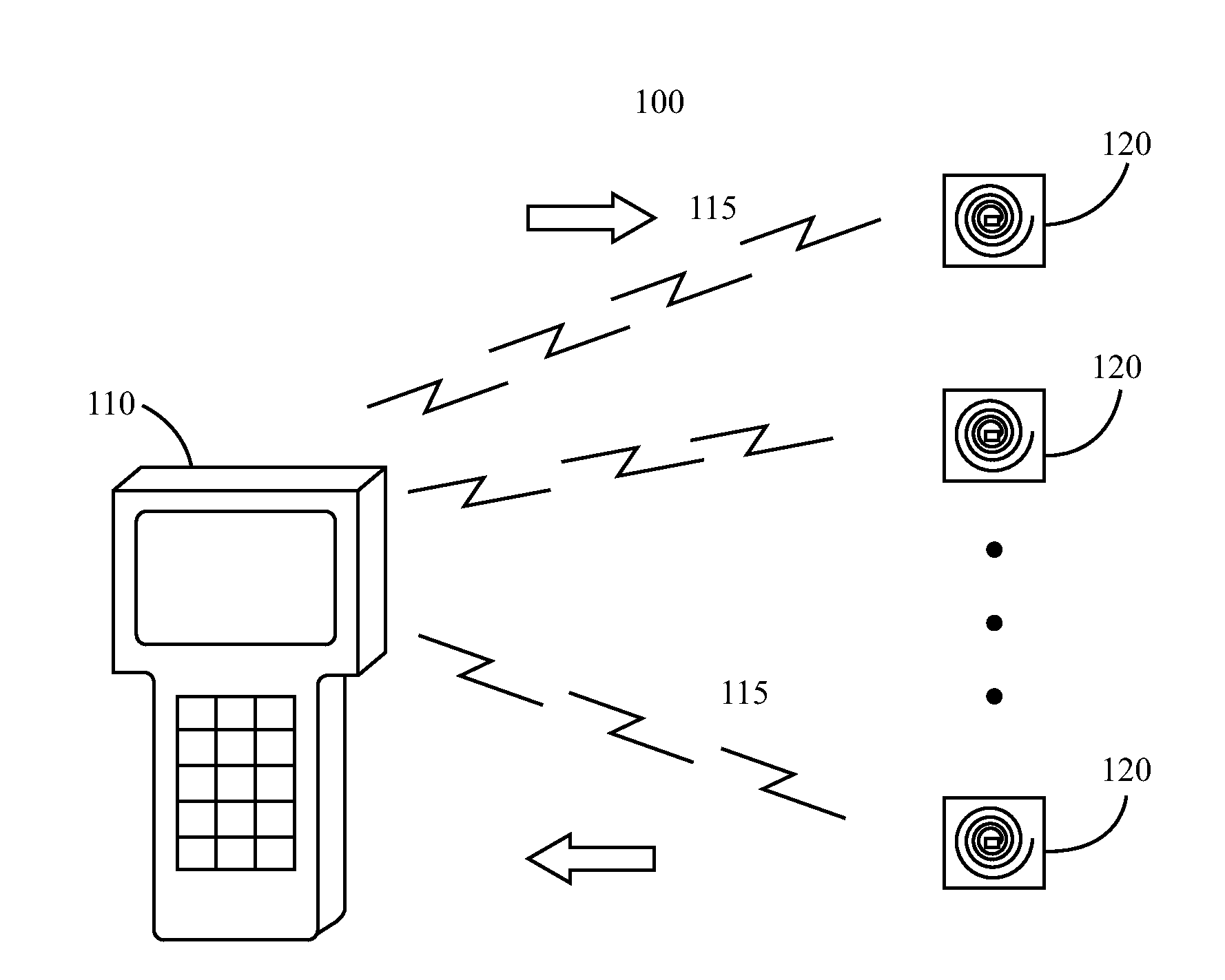
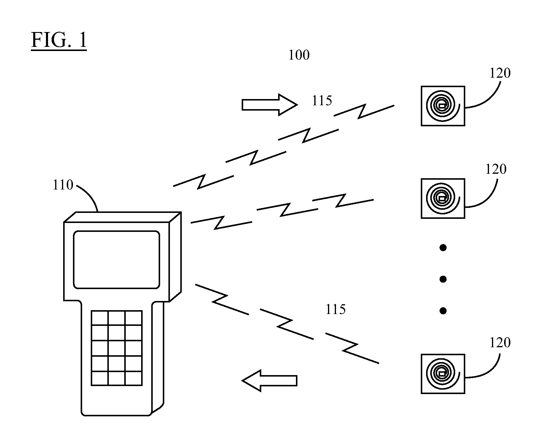
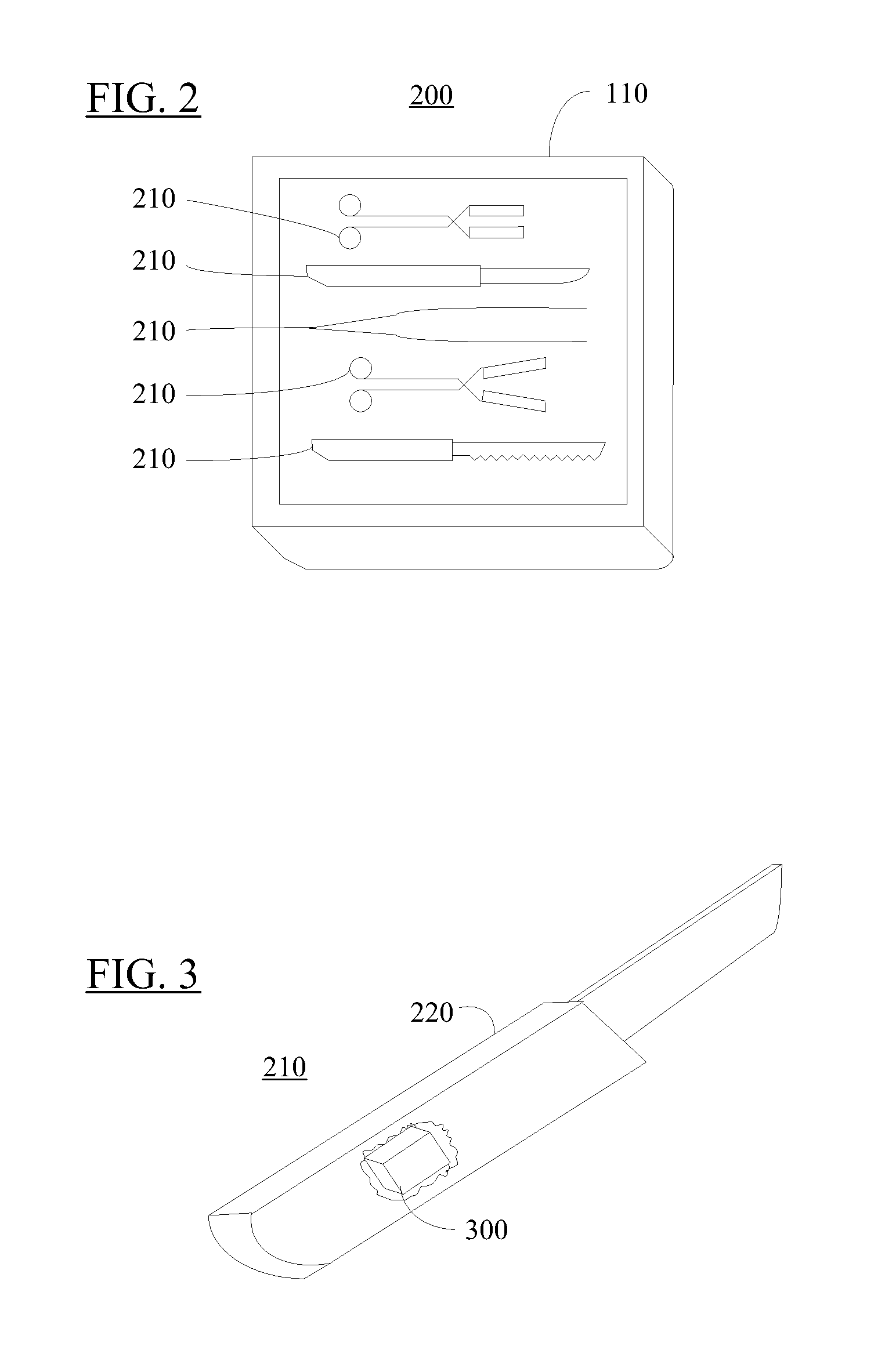
[0029]The following description is intended to convey a thorough understanding of the invention by providing specific embodiments and details involving automated identification and accounting of surgical instruments and instrument kits. It is understood, however, that the invention is not limited to these specific embodiments and details, which are exemplary only. It further is understood that one possessing ordinary skill in the art, in light of known systems and methods, would appreciate the use of the invention for its intended purposes and benefits in any number of alternative embodiments, depending upon specific design and other needs.

[0030]As used herein, the terms “surgical instrument” or simply “instrument” will refer to any type of standard surgical instrument, including scalpels, forceps, tweezers, clamps, spreaders, etc., as well as procedure and even discipline specific instrument such as, for example, orthopedic surgical equipment. The principles disclosed herein will a...


PUM


Abstract

Systems and methods for identifying surgical instruments by use of radio-frequency identification tags (RFID) are disclosed. In the systems and methods, each of a plurality of surgical instruments is provided with at least one RFID transponder tag storing identification information associated with the corresponding instrument. The tag may be adhered to, embedded, or potted within a portion of the instrument. Using an RFID reading device, a user may interrogate the tag, thereby identifying the particular instrument. This identification information may be used to index a database and retrieve a data record unique to that instrument. The systems and methods allow a user to track, inspect, and verify inbound and outbound surgical instruments, to assess, for example, the surgical instruments' duty life cycle usage.

Description

CROSS-REFERENCE[0001]This application is a continuation of U.S. patent application Ser. No. 11 / 116,379, filed on Apr. 28, 2005, the disclosure of which is hereby incorporated herein by reference in its entirety.FIELD OF THE INVENTION[0002]The invention generally relates to a method and apparatus for implementing radio frequency identification techniques, and more specifically, to a method and apparatus for tracking, inspecting and verifying orthopedic and surgical instruments in order to assess the surgical instruments' duty life cycle usage.DESCRIPTION OF RELATED ART[0003]A variety of methods exist for tracking and providing information about items. For example, inventory items typically carry printed labels providing information such as serial numbers, price, weight, and size. Some labels include data carriers in the form of machine-readable symbols that can be selected from a variety of machine-readable symbologies, such as bar code or area code symbologies. The amount of informa...

Claims


Application Information

Patent Timeline
Patent Type & Authority Applications(United States)
IPC IPC(8): H04Q5/22
CPCA61B19/00A61B2019/448A61B19/0271A61B50/33A61B90/00A61B90/98
Inventor TETHRAKE, STEVENELLIOTT, PAULNYCZ, JEFFREYVARNER, ROBERTPELO, MARK
Owner WARSAW ORTHOPEDIC INC
Why Eureka
Try Eureka