Projection Image Display Apparatus

Active Publication Date: 2010-07-15
SANYO ELECTRIC CO LTD
View PDF17 Cites 4 Cited by
  • Summary
  • Abstract
  • Description
  • Claims
  • Application Information

AI Technical Summary

Benefits of technology

[0010]In view of such an issue as above, the present invention contemplates a projection image display apparatus including a projection lens projecting from the main body and a lens hood surrounding the projection lens, that can prevent dust or the like foreign matters from entering from a top side into the main body and also protect the projection lens when the apparatus is carried and inadvertently has a projection lens unit brought into contact with a desk or the like.

Problems solved by technology

This helps dust or the like foreign matters to deposit and there is a large possibility that dust or the like foreign matters enter the main body of the projector.

Method used


Image

  • Projection Image Display Apparatus
  • Projection Image Display Apparatus
  • Projection Image Display Apparatus

Examples


first embodiment

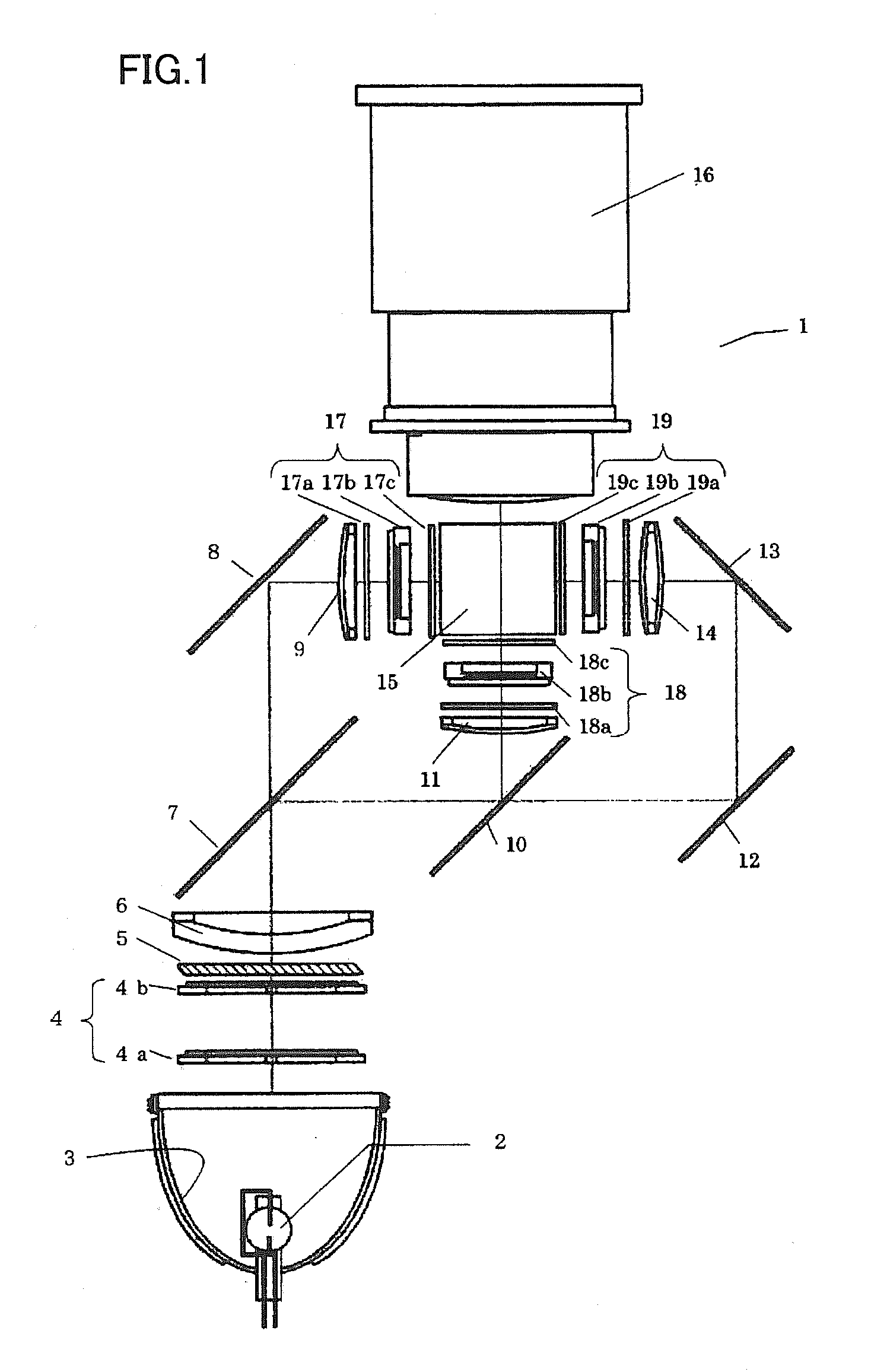
[0026]FIG. 1 shows a 3-plate liquid crystal optical engine 1 used in the present invention. In a light source 2 a light emitting unit is a super high pressure mercury lamp, a metal halide lamp, a xenon lamp or the like, and emits light which is in turn collimated by a parabola reflector 3 and thus emanates therefrom, and is guided to an integrator lens 4.

[0027]Integrator lens 4 is configured of a pair of lenses (fly eye lens) 4a and 4b. Each lens portion is adapted to guide the light that emanates from light source 2 to an entire surface of a liquid crystal light valve described hereinafter, to average partial, varying intensity present in light source 2 to reduce a difference in quantity of light between a center of a screen and a peripheral portion of the screen. Integrator lens 4 passes light, which in turn passes through a polarization conversion device 5 and a condenser lens 6 and is then guided to a first dichroic mirror 7.

[0028]Polarization conversion device 5 is configured o...

second embodiment

[0049]Hereinafter the present invention in a second embodiment will be described with with reference to FIG. 4. Note that components similar to those of the first embodiment are identically denoted and will not be described repeatedly.

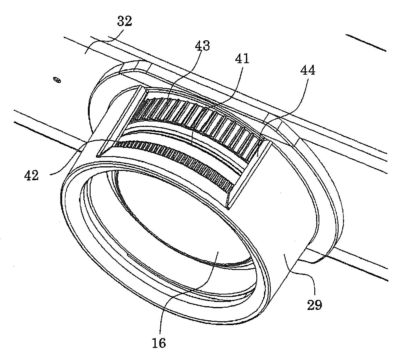
[0050]FIG. 4 is a lateral cross section of lens hood 29 of projector 21, as shown at a lateral side. In the first embodiment, opening 41 for the dial is formed at lens hood 29 through a top side at a single location, whereas in the second embodiment, it is formed at lens hood 29 through a top side and a bottom side.

[0051]This allows focusing dial 42 or zooming dial 43 to be held with fingers vertically and thus rotated further smoothly.

third embodiment

[0052]Hereinafter the present invention in a third embodiment will be described with reference to FIG. 5. Note that components similar to those of the first or second embodiment are identically denoted and will not be described repeatedly.

[0053]FIG. 5 is a lateral cross section of lens hood 29 of projector 21, as shown at a lateral side. The third embodiment, as compared with the second embodiment, provides front panel 32 having an opening 51 (a first opening) for the projection lens, that has a circumferential surface with urethane 52 (a dustproof member) attached thereto. This can close a gap formed between opening 51 for the projection lens and projection lens 16 and also prevent dust or the like foreign matters from entering through the gap otherwise formed between opening 51 for the projection lens and projection lens 16.

[0054]In the first embodiment opening 41 for the dial is provided at lens hood 29 through a top side and in the second embodiment opening 41 for the dial is pr...


PUM


Abstract

A projection image display apparatus has a front panel, a projection lens, a lens hood, and a lens dial. The front panel has an opening for the projection lens. The projection lens projects through the opening for the projection lens. The lens hood covers the projection lens circumferentially, and has an opening spaced from an end of the lens hood for a dial. The lens dial is provided for adjusting focusing or zooming. It is provided at a circumference of the projection lens and exposed through the opening for the dial. The apparatus can thus avoid dust or the like foreign matters otherwise entering from a top side thereof into its main body, and also protect the projection lens when the apparatus is carried and inadvertently has a projection lens unit brought into contact with a desk or the like.

Description

CROSS REFERENCE TO RELATED APPLICATIONS[0001]This application claims priority to Japanese Patent Application No. 2009-004570, filed Jan. 13, 2009, which application is incorporated herein by reference in its entirety.BACKGROUND OF THE INVENTION[0002]1. Field of the Invention[0003]The present invention relates to projection image display apparatuses having a lens hood for a projection lens.[0004]2. Description of the Related Art[0005]Registered Design No. 1289596 discloses a projector, as shown in FIG. 6. More specifically, the projector has a projection lens 101 projecting through an opening 103 formed at a front panel 102 for the projection lens. Projection lens 101 has its circumference covered with a lens hood 104. A lens adjustment tab 105 is provided on the apparatus's main body at a top side.[0006]When the projector configured as above is carried, and inadvertently brought into contact with a desk or the like resulting in an impact or a load given to projection lens 101, proje...

Claims


Application Information

Patent Timeline
IPC IPC(8): G03B3/00
CPCG03B3/00
Inventor ODA, YOSHITERUSUZUKI, YOSHIHO
Owner SANYO ELECTRIC CO LTD
Why Eureka
Try Eureka