Modular LED light system and method

Inactive Publication Date: 2010-07-15
SHOUSHTARI HAMID
View PDF3 Cites 26 Cited by
  • Summary
  • Abstract
  • Description
  • Claims
  • Application Information

AI Technical Summary

Benefits of technology

[0023]It is yet a further object of this invention, to provide an assembleable LED based light bulb, which may be adapted to engage any of a plurality of different types of conventional fixtures to insure easy and rapid deployment in the installed base of such fixtures.
[0024]I

Problems solved by technology

Unfortunately, the modern light bulbs conventionally employed are substantially the same in design and function as the bulbs first invented by Mr. Edison, in that they employ a resistive load which creates light and heat when an electrical current is communicated across a small filament inside of a bulb housing.
These resistive bulbs consume a large amount of energy and produce an equally large amount of heat due to their resistive load nature.
With energy prices ever rising, and the supply of energy such as fossil fuels becoming harder to obtain, the billions of such resistive load light bulbs, consume an inordinate amount of energy.
Additionally, in homes and offices situated in climates where heat is an issue, the addition of heat from multiple light bulbs exacerbates the problem.
Further, the energy consumption to both operate the light bulbs and in many cases, cool the building employing them, has become a major factor in home and business budgets.
This budgetary issue can only get worse over time since the cost for electricity will continue to escalate along with the cost of fossil fuels which are employed to run generators to produce and communicate electrical power to these commercial and resident

Method used


Image

  • Modular LED light system and method
  • Modular LED light system and method
  • Modular LED light system and method

Examples


Example

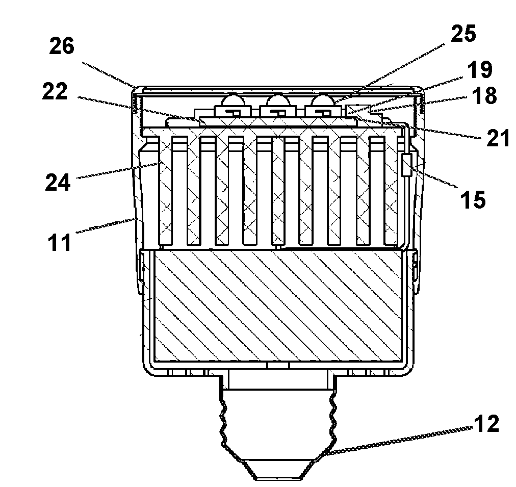
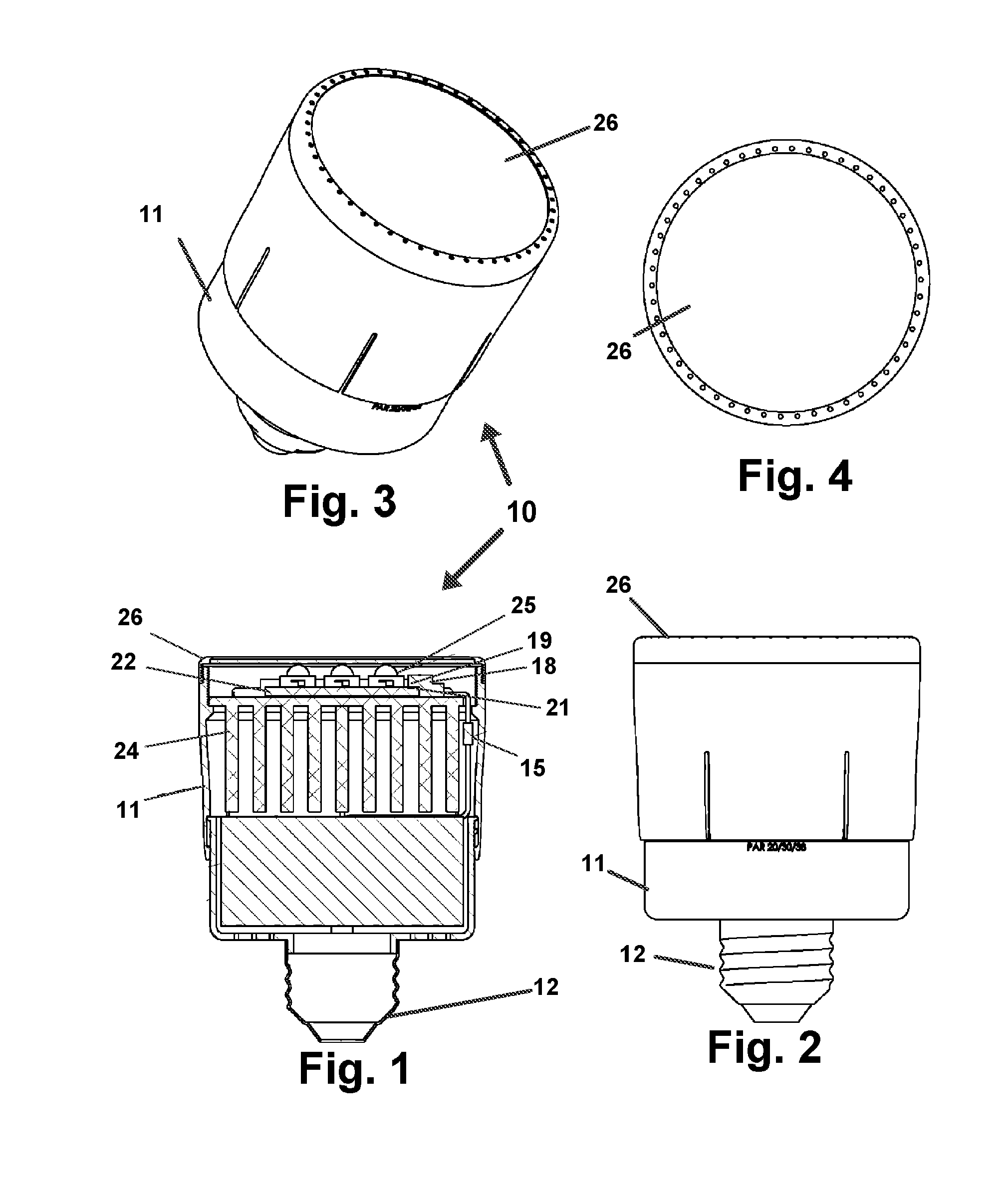
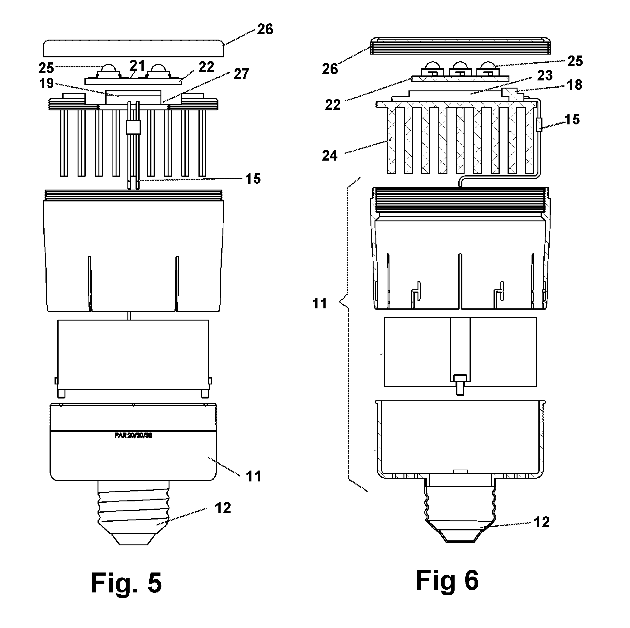
[0046]Referring now to the drawings 1-19, wherein similar parts of the invention are identified by like reference numerals, there is seen in FIG. 1 the base 11, having a means for electrical engagement with a lighting fixture shown in the form of a conventional screw in electrical engagement component 12. Of course any means for operative engagement with a conventional light fixture, such as those depicted in FIGS. 18 and 19, may be employed so as to provide electrical power to the device 10 and allow engagement into conventional fixtures. This will insure wide deployment in a short time and increased ecological benefit from reduced energy use.

[0047]The base 11 so engaged communicates power from the fixture engaged with the engagement component 12 using wires 15 or other electrical means to communicate electrical power to a housing 18 which employs electrical contacts 19 in positions to register and engage with mating contacts 21 on the circuit board 22.

[0048]The employment of circu...


PUM


Abstract

A modular device and system for formation of an LED based light bulb. The formed bulb is assembled from interchangeable components which adapted it for engagement to any of a plurality of conventional bulb light fixture connectors. Diffusors and hoods are also attachable to change the diffusion and focus of light emitted from the formed bulb. A plurality of different circuit boards may be engaged to a socket positioned on a heat sink to increase or decrease emitted light. The socket will only electrically engage the circuit board if the heat sink will dissipate the anticipated heat generated by the circuit board.

Description

[0001]This application is a Continuation in Part application of U.S. Provisional Application No. 61 / 143,715 filed Jan. 9, 2009 which is incorporated herein in its entirety by reference.FIELD OF THE INVENTION[0002]The disclosed device relates to lighting for home and commercial venues. More particularly it relates to a device and method which allow for the employment of Light Emitting Diods (LED's) as a means for projection of illumination. The device is provided in a modular form allowing for users to configure multiple types of light bulbs from interchangeable components. Employing this modular scheme, the LED's are replaceable and may be upgraded or downgraded depending on the lighting requirements in the fixture in which the device is engaged.BACKGROUND OF THE INVENTION[0003]Throughout the world, the electric light bulb has provided illumination to homes and businesses for decades since the first commercial bulbs invented by Thomas Edison. Unfortunately, the modern light bulbs co...

Claims


Application Information

Patent Timeline
IPC IPC(8): F21S4/00
CPCF21Y2101/02F21V19/003F21V19/045F21V29/763F21K9/137F21V29/507F21K9/135F21K9/232F21K9/233F21Y2115/10F21V19/04
Inventor SHOUSHTARI, HAMID
Owner SHOUSHTARI HAMID
Why Eureka
Try Eureka