Image processing method, image processing apparatus, and image processing program

a three-dimensional image and image processing technology, applied in the field of image processing methods, image processing apparatuses, image processing programs, can solve the problems of difficult radiologists to diagnose bone regions that require careful viewing, difficult for radiologists to perform diagnosis, etc., to facilitate the diagnosis of bone regions

Inactive Publication Date: 2010-07-15
FUJIFILM CORP
View PDF7 Cites 36 Cited by
  • Summary
  • Abstract
  • Description
  • Claims
  • Application Information

AI Technical Summary

Benefits of technology

[0042]In the image processing apparatus, the image processing method, and the image processing program of the present invention, a planar exploded pseudo three dimensional medical image is generated by executing an intensity projection method in a radial manner from the center line toward the surface of the subject's body, and the generated pseudo three dimensional medical image is displayed. Therefore, a pseudo three dimensional medical images that facilitates diagnosis of bone regions, while enabling the position of the bone region within the subject as a whole to be understood, can be generated and displayed.
[0043]A configuration may be adopted, wherein specified points are input within medical images which are displayed, the positions of corresponding points within pseudo three dimensional medical images that correspond to the specified points within the medical images are calculated, and markers that indicate the calculated corresponding points are displayed along with the pseudo three dimensional medical images. In this case, positions within t

Problems solved by technology

However, because the density values of bone regions represented in medical images is high, there is a tendency for the bone regions to become particularly emphasized in pseudo three dimensional medical images which are generated by the MIP method, which cause difficulties for radiologists in performing diagnosis.
Therefore, there is a problem that the bone regions cannot be diagnosed.
However, because the thoracic bones (particularly the ribs, the breastbone, and the thoracic vertebrae) are present s

Method used


Image

  • Image processing method, image processing apparatus, and image processing program
  • Image processing method, image processing apparatus, and image processing program
  • Image processing method, image processing apparatus, and image processing program

Examples


Embodiment Construction

[0051]Hereinafter, an embodiment of the present invention will be described with reference to the attached drawings.

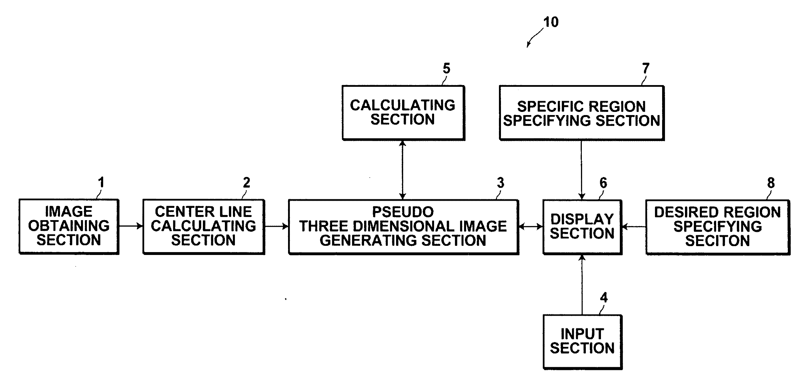
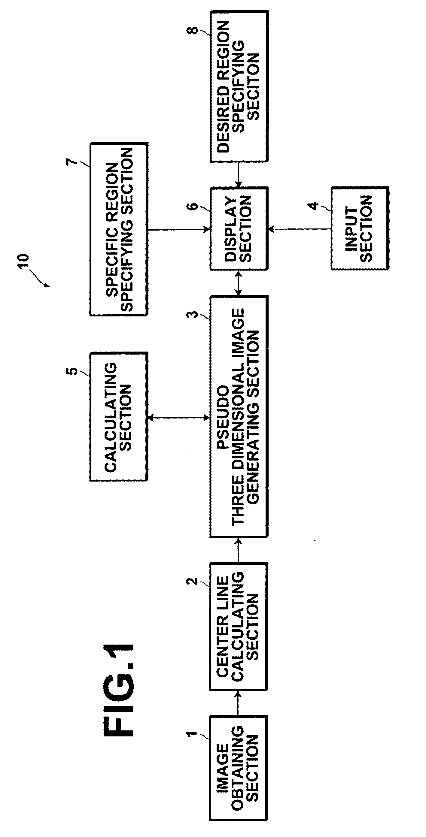
[0052]An image processing apparatus 10 illustrated in FIG. 1 is equipped with: an image obtaining section 1, for obtaining a plurality of medical images (axial) that represent transverse sections of a subject and include the surface of the body of the subject, which have been imaged in advance; a center line calculating section 2, for calculating a center line that connects the approximate centers of subject regions pictured in the plurality of medical images; a pseudo three dimensional medical image generating section 3, for generating a planar exploded pseudo three dimensional medical image by executing an intensity projection method in a radial manner from the center line toward the surface of the subject's body; a display section 6, for displaying the generated pseudo three dimensional medical image and / or at least one of the plurality of medical images; an input s...


PUM


Abstract

An image processing apparatus includes: an image obtaining section for obtaining medical images (axial images), which are imaged in advance, that represent transverse cross sections of a subject; a center line calculating section, for calculating a center line that connects the centers of subject regions within the medical images; a pseudo three dimensional medical image generating section, for generating a planar exploded pseudo three dimensional medical image, by executing an intensity projection method on image data constituted by at least a plurality of the subject regions from the center line radially outward toward the surface of the subject's body such that thoracic bones in the front to back direction of the projection direction of the subject are not displayed in an overlapping manner; and a display section, for displaying at least one of the pseudo three dimensional medial image and the plurality of medical images.

Description

BACKGROUND OF THE INVENTION[0001]1. Field of the Invention[0002]The present invention is related to an image processing method for generating pseudo three dimensional medical images. Particularly, the present invention is related to an image processing apparatus, an image processing method, and a computer readable medium, on which an image processing program for generating pseudo three dimensional medical images from a plurality of medical images by executing an intensity projection method is recorded.[0003]2. Description of the Related Art[0004]In the medical field, pseudo three dimensional medical images are generated by executing IP (Intensity Projection) methods that enable three dimensional medical images to be formed with respect to a plurality of medical images.[0005]The IP methods are processes by which pixels having the maximum values (alternatively, minimum values or specified values) from among corresponding pixels within all original medical images, which are the targets...

Claims


Application Information

Patent Timeline
IPC IPC(8): G06K9/00G06T17/00A61B5/055A61B6/03
CPCG06T7/606G06T11/008G06T15/08G06T2210/41G06T2207/30008G06T2207/30172G06T2207/10072G06T7/66
Inventor MORIYA, YOSHIYUKI
Owner FUJIFILM CORP
Why Eureka
Try Eureka