Conductive Paste, Solar Cell Manufactured Using Conductive Paste, Screen Printing Method and Solar Cell Formed Using Screen Printing Method

a technology of solar cells and conductive pastes, which is applied in the manufacture of printed circuits, non-conductive materials with dispersed conductive materials, semiconductor devices, etc., can solve the problems of large value of wiring, inability to obtain desired printing results, and inability to obtain printing shapes in some cases, so as to prevent bleeding of conductive pastes, achieve high printing accuracy, and easily make printing pastes

Inactive Publication Date: 2010-07-15
KYOCERA CORP
View PDF8 Cites 6 Cited by
  • Summary
  • Abstract
  • Description
  • Claims
  • Application Information

AI Technical Summary

Benefits of technology

[0020]It is possible to suppress bleeding of the conductive paste and clogging of the conductive paste in a mesh part during printing, easily make the printing paste (that is, the conductive paste printed on an object to be printed) thicker and improve deficiency in printing.
[0023]Since the filling squeegee only serves to fill the paste previously spread over the screen by using an another member (that is, the scraper) into the pattern hole, the filling processing can be performed very efficiently, resulting in substantial reduction in processing time.
[0025]Therefore, an object of the present invention is to provide an art of preventing bleeding of the conductive paste and clogging of the conductive paste in a mesh part in screen printing and easily making the printing paste (that is, the conductive paste printed on the object to be printed) thicker while obtaining printing wiring with high accuracy.
[0026]Another object of the present invention is to provide a solar cell manufactured by using the conductive paste capable of preventing bleeding of the conductive paste and clogging of the conductive paste in a mesh part in screen printing and easily making the conductive paste printed on the object to be printed thicker while obtaining printing wiring with high accuracy.
[0027]Another object of the present invention is to provide a screen printing method of obtaining a printed matter having stable shape and thickness of the printed paste in spite of short printing time.
[0028]Another object of the present invention is to provide a solar cell manufactured according to a screen printing method of obtaining a printed matter having stable shape and thickness of the printed paste in spite of short printing time.

Problems solved by technology

However, since the process time for filling the paste into the pattern hole of the screen becomes shorter as the moving speed of the scraper is increased, the paste cannot be fully filled into the pattern hole, causing a problem that a desired printing result (that is, printing shape) cannot be obtained in some cases.
For example, in printing wiring on the object to be printed by use of the conductive paste, when the thickness of the wiring partially becomes thinner due to the above-mentioned problem, a resistance value of the wiring becomes larger, thereby leading to functional disorder of the wiring such as generation of heat.
Thus, it is extremely difficult to increase the moving speed of the scraper.
However, when the general conductive paste film is formed on the substrate according to the general screen printing method by using the screen having the printing pattern hole and the resin squeegee as described above, bleeding occurs in the printed figure (that is, the printing shape formed by the conductive paste) and / or clogging occurs in the mesh part of the screen.
These problems becomes pronounced especially when the manufacturer attempts to make a minute pattern of the conductor circuit and causes failure of wiring due to a break in the circuit as well as variation in and defects of characteristics of the solar cell.
It is considered that the clogging of the mesh part is caused by a release property of the conductive paste filled into the printing pattern hole, that is, a viscous component in the viscosity of the conductive paste under the shear rate applied when the conductive paste is transferred to the substrate.
Accordingly, large bleeding is generated and electrodes with enough thickness cannot be formed.
As described above, when the above-mentioned conductive paste is printed on the substrate, the light-receiving area is decreased due to large bleeding that occurs in the coated film after printing and enough thickness of the electrodes cannot be obtained, thereby increasing resistance loss of the electrodes.
Thus, the solar cell having high conversion efficiency cannot be manufactured.

Method used


Image

  • Conductive Paste, Solar Cell Manufactured Using Conductive Paste, Screen Printing Method and Solar Cell Formed Using Screen Printing Method
  • Conductive Paste, Solar Cell Manufactured Using Conductive Paste, Screen Printing Method and Solar Cell Formed Using Screen Printing Method
  • Conductive Paste, Solar Cell Manufactured Using Conductive Paste, Screen Printing Method and Solar Cell Formed Using Screen Printing Method

Examples


Embodiment Construction

[0037]Hereinafter, a preferred embodiment of the present invention will be described in detail with reference to figures.

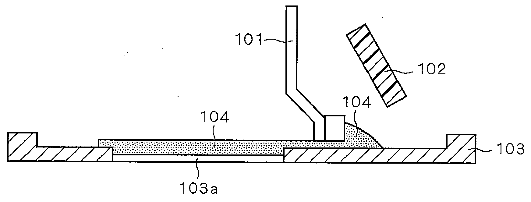
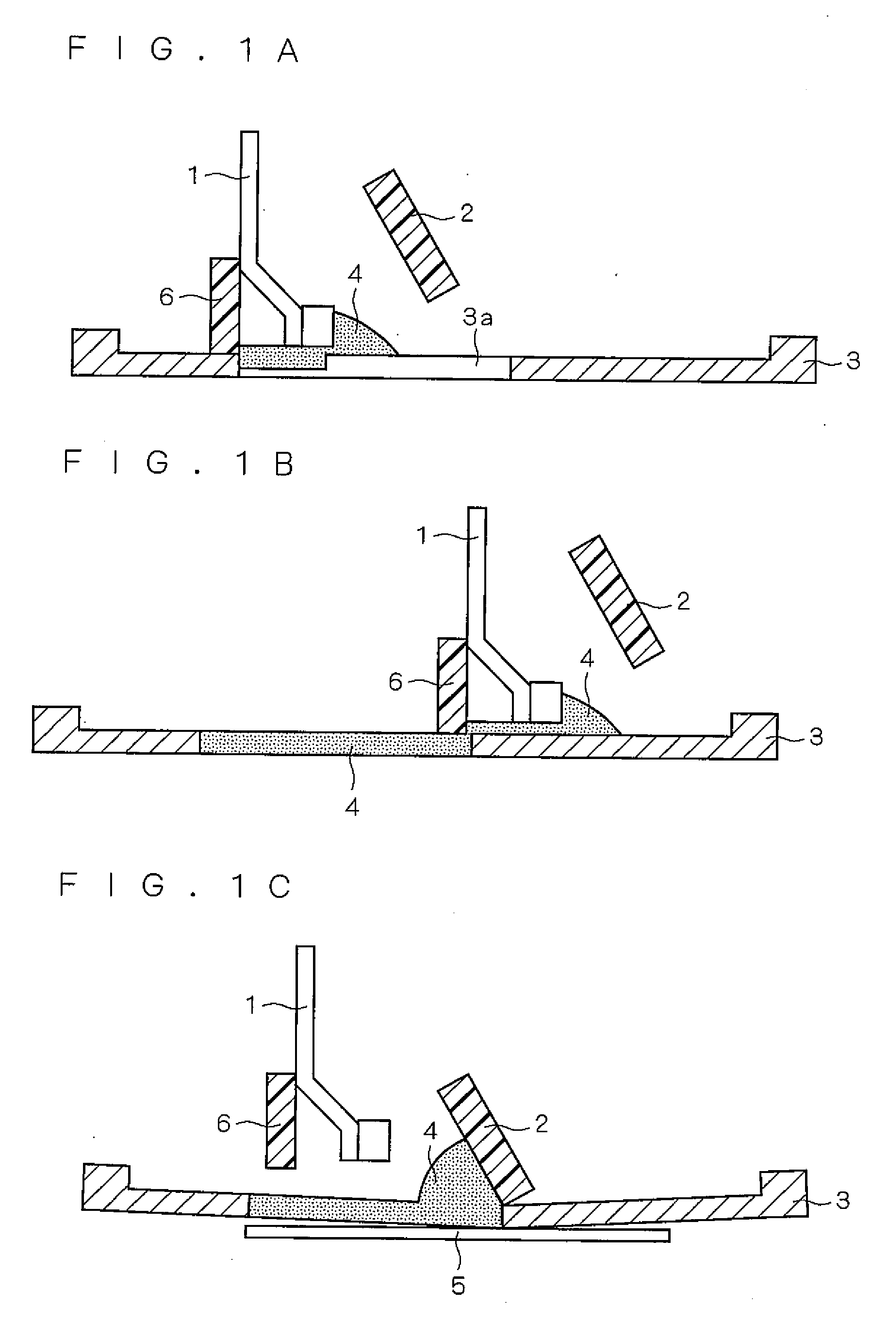
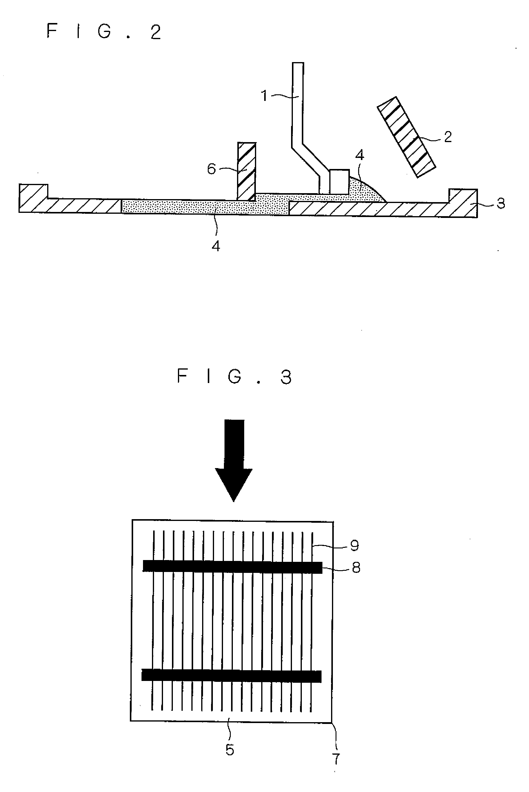
[0038]A preferred embodiment of a printing method of the present invention will be described with reference to FIG. 1 A to FIG. 1C. FIG. 1A to FIG. 1C are views showing first to third steps in a screen printing method in accordance with the preferred embodiment of the present invention, respectively. These figures show a scraper 1, a printing squeegee 2, a screen 3, a pattern hole 3a, a paste 4, an object to be printed 5 and a filling squeegee 6. A screen printer used in the screen printing method in accordance with this embodiment has mainly a scraper 1, a first squeegee 2, a screen 3 and the second squeegee 6, and prints the paste 4 on the object to be printed 5 via the screen 3 provided with the pattern hole 3a. The scraper 1 is a member for spreading the paste 4 on the surface of the screen 3. The second squeegee 6 is a squeegee (also referred to as the “filli...


PUM


Abstract

The conductive paste contains a conductive metal powder and an organic vehicle. The conductive paste has characteristics that the viscosity falls within the range of 200 Pa·s to 350 Pa·s when the shear rate of 10 s−1 is applied and within the range of 80 Pa·s to 120 Pa·s when the shear rate of 40 s−1 is applied under 25° C. and magnitudes of a storage elastic modulus G′ and a loss elastic modulus G″ are reversed when distortion applied to the conductive paste at the frequency of 1 Hz is varied from 0 to 20%.

Description

[0001]This application is based on application Nos. JP2005-208419 and JP2005-249319 filed in Japan, the contents of which are hereby incorporated by reference.BACKGROUND OF THE INVENTION[0002]1. Field of the invention[0003]The present invention relates to a screen printing method, a solar cell formed using the screen printing method, a method for forming a printing substrate on which a conductor circuit represented by a solar cell, especially a method for manufacturing a solar cell using a conductive paste for printing.[0004]2. Description of the Background Art[0005]FIG. 6 shows a conventional screen printing method.[0006]First, a scraper 101 is lowered on the screen 103 and a paste 104 located at one end of the screen 103 (printing termination end) is moved to the other end (printing starting end). At this time, a part of the paste 104 is filled into a pattern hole 103a of the screen 103.[0007]Next, the scraper 101 rises and an object to be printed is sent to a position about 0.5 t...

Claims


Application Information

Patent Timeline
Patent Type & Authority Applications(United States)
IPC IPC(8): H01L31/18H01L21/3205
CPCH01B1/22H01L31/022425Y02E10/50H05K3/1216H05K1/092
Inventor SAKAMOTO, TOMONARIHISAMOTO, KAZUTERUETOU, HIROTOSHI
Owner KYOCERA CORP
Why Eureka
Try Eureka