Separator for separating oil mist from the crankcase ventilation gas of an internal combustion engine, and functional module and internal combustion engine comprising a separator

Active Publication Date: 2010-07-22
HENGST WALTER
View PDF12 Cites 131 Cited by
  • Summary
  • Abstract
  • Description
  • Claims
  • Application Information

AI Technical Summary

Benefits of technology

[0006]For the present invention, the objective accordingly is to provide a separator of the initially indicated type which avoids the above presented disadvantages and in which the rotary drive provides—especially with a specified drive power—for a high speed of the centrifugal rotor and thu

Problems solved by technology

At first sight, the rotary drive by means of at least one thrust nozzle on the shaft appears to be relatively complex because pressurized lubrication oil must be passed to the or each of the thrus

Method used


Image

  • Separator for separating oil mist from the crankcase ventilation gas of an internal combustion engine, and functional module and internal combustion engine comprising a separator
  • Separator for separating oil mist from the crankcase ventilation gas of an internal combustion engine, and functional module and internal combustion engine comprising a separator
  • Separator for separating oil mist from the crankcase ventilation gas of an internal combustion engine, and functional module and internal combustion engine comprising a separator

Examples


Embodiment Construction

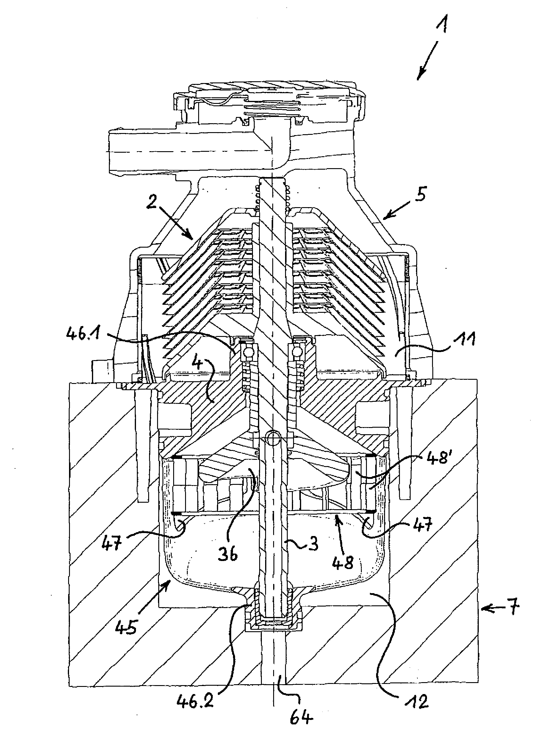
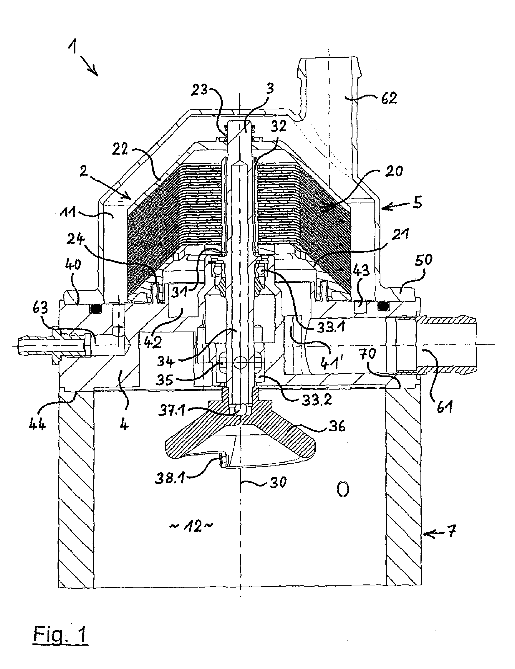
[0084]FIG. 1 of the drawing shows a first separator 1 in a longitudinal section which extends in an essentially vertical plane, wherein the separator 1 is flanged to an internal combustion engine 7 here also presented sectionally in a very small part.

[0085]The separator 1 comprises in its upper area a gas purification chamber 11 and in its lower area a drive chamber 12. The gas purification chamber 11 and the drive chamber 12 are separated from each other by a base plate 4. The gas purification chamber 11 is limited towards the outside by a cover 5 which is sealingly set onto the upper side 40 of the base plate 4.

[0086]The drive chamber 12 located under the base plate 4 lies within the internal combustion engine 7 and is laterally and downwardly limited by it.

[0087]A rotatable shaft 3 extends through the base plate 4 and is provided in an upper bearing 33.1, here a rolling bearing, and in a bottom bearing 33.2, here a friction bearing. The two bearings 33.1 and 33.2 are both arrange...


PUM

PropertyMeasurementUnit
Fractionaaaaaaaaaa
Angleaaaaaaaaaa
Angleaaaaaaaaaa

Abstract

A separator for separating oil mist from the crankcase ventilation gas of an internal combustion engine, especially of a motor vehicle. The separator includes a gas purification chamber inside which a rotatably mounted centrifugal rotor is arranged. The gas purification chamber has a crude gas inlet, a pure gas outlet, and an oil outlet. The crankcase ventilation gas can be conducted into a radially internal zone of the centrifugal rotor via the crude gas inlet, while pure gas that is liberated from oil mist can be discharged from the gas purification chamber via the pure gas outlet, and oil separated from the gas can be discharged from the gas purification chamber via the oil outlet. The separator further includes a rotary drive for the centrifugal rotor. The rotary drive is disposed in a drive chamber of the separator, can be operated using pressurized lubrication oil of the internal combustion engine, and is connected to the centrifugal rotor by means of a shaft extending from the drive chamber into the gas purification chamber, from which the drive chamber is separated. The rotary drive is formed by at least one thrust nozzle which is connected to the shaft and to which the pressurized lubrication oil of the internal combustion engine can be fed. The separator includes at least one part of a base that forms the separation between the gas purification chamber and the drive chamber and extends into the drive chamber, the part of the base being fitted with a seat for a bearing of the shaft. The bearing is located at a distance from the centrifugal rotor.

Description

BACKGROUND OF THE INVENTION[0001]The invention relates to a separator for separating oil mist from the crankcase ventilation gas of an internal combustion engine, especially of a motor vehicle; with a gas purification chamber inside which a rotatably mounted centrifugal rotor is arranged. The gas purification chamber has a crude gas inlet, a pure gas outlet, and an oil outlet. The crankcase ventilation gas can be conducted into a radially internal zone of the centrifugal rotor via the crude gas inlet, while pure gas liberated from oil mist can be discharged from the gas purification chamber via the pure gas outlet, and oil separated from the gas can be discharged from the gas purification chamber via the oil outlet. The separator comprises a rotary drive for the centrifugal rotor, the rotary drive being arranged in a drive chamber of the separator, the drive chamber being separately arranged from the gas purification chamber, and the drive can be operated using pressurized lubricati...

Claims


Application Information

Patent Timeline
IPC IPC(8): F01M11/03B01D45/14F01M1/06
CPCB04B5/005B04B5/12B04B7/14F01M2013/0422B04B2005/125F01M13/04B04B9/06
Inventor BAUMANN, DIETERVINKELAU, CHRISTIANSCHLAMANN, GUIDO
Owner HENGST WALTER
Why Eureka
Try Eureka