Time-frequency fusion digital pixel sensor

a digital pixel sensor and time-frequency fusion technology, applied in the field of image sensors, can solve the problems of low light insensitivity, poor noise floor, high digital power consumption, etc., and achieve the effects of reasonable noise floor, reasonable noise floor, and high dynamic rang

Active Publication Date: 2010-07-22
RAYTHEON CO
View PDF5 Cites 65 Cited by
  • Summary
  • Abstract
  • Description
  • Claims
  • Application Information

AI Technical Summary

Benefits of technology

[0006]A potential technical advantage of some embodiments of the invention is the ability to maintain all the benefits associated with a standard light-to-time and light-to-frequency conversion while eliminating their disadvantages. Such benefits include having a high dynamic range, reasonable noise floor, and low digital power consumption as found in light-to-frequency conversion sensors. While maintai

Problems solved by technology

However, a variety of benefits and disadvantages are associated with each of these processes.
While light-to-frequency conversions have high dynamic ranges and low power consumptions, th

Method used


Image

  • Time-frequency fusion digital pixel sensor
  • Time-frequency fusion digital pixel sensor

Examples


Embodiment Construction

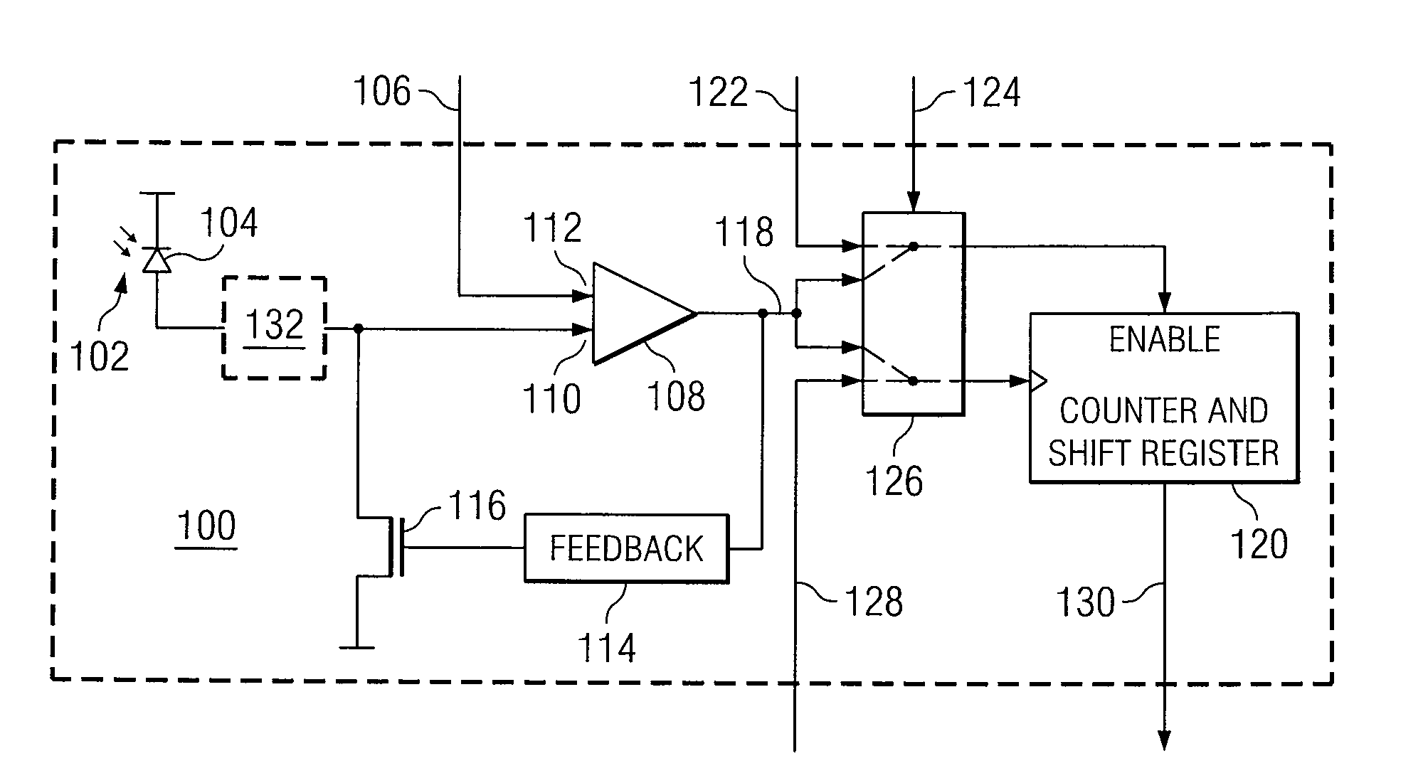
[0010]FIG. 1 illustrates an example architecture for time-frequency fusion digital pixel sensor 100. In sensor 100, a detector 104 absorbs incident light 102 and generates a voltage signal provided to an input 110 of a comparator 108. The voltage signal at input 110 is proportional to an intensity of light 102. During a first phase of the sensor 100 operation, the voltage present at an input 112 of comparator 108 is fixed and comparator 108 generates pulses at an output 118 whenever the voltage at input 110 passes above the voltage at input 112. A feedback loop 114 resets the voltage at input 110 each time a pulse is generated. During the first phase, a most significant bits section of a counter 120 counts the number of pulses generated at output 118. If an amount of light 102 absorbed at detector 104 is relatively intense, the voltage present at input 110 will increase relatively rapidly and pass above the voltage at input 112 relatively often, producing a relatively high frequency...


PUM


Abstract

Light is converted to an electric signal by performing a light-to-frequency conversion of the light received during a first phase of operation. Following the first phase of operation, a light-to-time conversion is performed on light received during a second phase of operation. Following the second phase of operation a digital representation of the light is generated in response to the light-to-frequency conversion and the light-to-time conversion.

Description

TECHNICAL FIELD OF THE DISCLOSURE[0001]This disclosure generally relates to image sensors and more particularly to a time-frequency fusion digital pixel sensor.BACKGROUND OF THE DISCLOSURE[0002]A digital pixel sensor uses in-pixel analog-to-digital conversion to convert an optical image to an electrical signal. Two techniques of performing such a conversion are light-to-frequency conversion and light-to-time conversion. Light-to-frequency conversion operates using a light-controlled oscillator to generate an output waveform, the frequency of which is proportional to the light intensity of the image. Light-to-time conversion uses a single-slope analog-to-digital conversion to generate a digital value that corresponds to the light intensity of the image. Both light-to-frequency conversions and light-to-time conversions have been used in image sensing technologies. However, a variety of benefits and disadvantages are associated with each of these processes. While light-to-frequency con...

Claims


Application Information

Patent Timeline
IPC IPC(8): H01J40/14
CPCH03M1/145H03M1/56H04N5/37455H04N5/35572H03M1/60H04N25/587H04N25/772
Inventor VEEDER, KENTON T.
Owner RAYTHEON CO
Why Eureka
Try Eureka