Heat sink with helical fins and electrostatic augmentation

a technology of electrostatic augmentation and heat sink, which is applied in the direction of lighting and heating apparatus, semiconductor/solid-state device details, fixed installation, etc., can solve the problems of inconvenient shape of air passage, no moving parts, and short improvement time, and achieve excellent air flow

Inactive Publication Date: 2010-07-22
LIGHT PRESCRIPTIONS INNOVATORS
View PDF8 Cites 34 Cited by
  • Summary
  • Abstract
  • Description
  • Claims
  • Application Information

AI Technical Summary

Benefits of technology

[0008]The heat-sink geometry of the present application makes it possible to offer better heat removal than conventional configurations, at any orientation, and therefore provides a way, for the first time, of producing solid state lamps that can replace a wide range of incandescent bulbs.
[0010]Because of the stagnant air layer that forms inside a ceiling can, even this improvement may fall short at even higher power levels, because in order to establish a chimney effect the heat sink must remain at a higher temperature than the air at the top of the can. Thus a further preferred embodiment also utilizes an ionic air mover to push air downwards through an outer passage separate from the passages of the helical heat sink. Even a very low-velocity air mover can greatly enhance heat-sink performance over that of natural convection unaided. A further 25° C. temperature drop was obtained from a tenth-meter per second downward air current, or under a quarter mile per hour, a barely perceptible breeze that will be unnoticeable beyond the can. (In fact, the Ionic Breeze® air cleaner achieves ten times this velocity, as measured by the inventors.) The hybrid system was able to maintain an LED junction temperature of just 50° C. (25° C. above the ambient temperature of the room, which is assumed to be 25° C.). By comparison the junction temperature using the prior art vertical fins was 90° C., forty degrees hotter and definitely life-shortening. Overall, the new hybrid system dropped the junction temperature by 36° C. in the 10 Watt LED downlight, a very significant improvement.
[0012]Most importantly for the present application, moreover, is that the entrained flow can force hot air to move downward against gravity. This can keep the heat sink nearer ambient temperature. Conventional neon-sign technology can supply small enough power supplies for this function, in the 5-10 kV range. Less than a tenth of a Watt can generate the aforementioned current of a tenth meter per second, many times more thermally effective than natural convection. It was determined that the force for the electrostatic air-moving system only needed to be very small to induce excellent air flow in the system. That is, the combination of an upward thermal stack and a downward flow from electro-static air movement work together in a synergetic manner, the combined effect is greater than the sum of the parts. For example, simulations in COSMOS showed that the junction temperature of the LEDs of 62° C. could be achieved for the same hybrid system mentioned above if the air flow from the electro-static component is reduced to only 0.050 m / s (approximately one tenth of a mile per hour, only one-twentieth the air flow speed of conventional ionic air cleaners).

Problems solved by technology

Because of the stagnant air layer that forms inside a ceiling can, even this improvement may fall short at even higher power levels, because in order to establish a chimney effect the heat sink must remain at a higher temperature than the air at the top of the can.
While there are numerous methods of air-moving, those that involve moving parts will find difficulty in operating all the way around the periphery of the helical heat sink, with multiple small air movers being required, greatly increasing cost and complexity.
The method utilized herein, however, has no moving parts and can cover inconvenient shapes of air-passages (such as an annular cylinder).

Method used


Image

  • Heat sink with helical fins and electrostatic augmentation
  • Heat sink with helical fins and electrostatic augmentation
  • Heat sink with helical fins and electrostatic augmentation

Examples


Embodiment Construction

[0022]A better understanding of various features and advantages of the present invention will be obtained by reference to the following detailed description and accompanying drawings, which set forth illustrative embodiments in which certain of the principles of the invention are utilized.

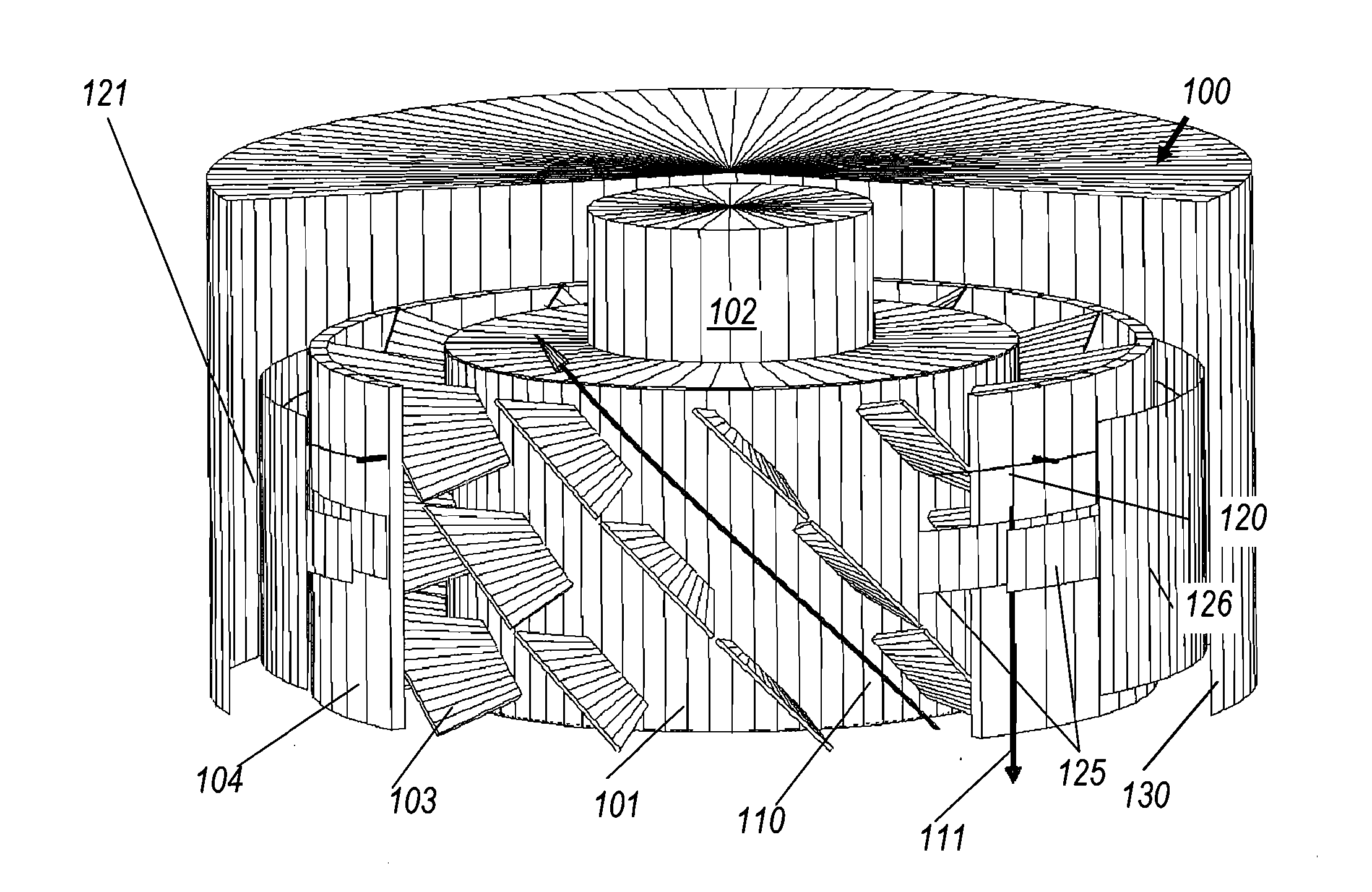
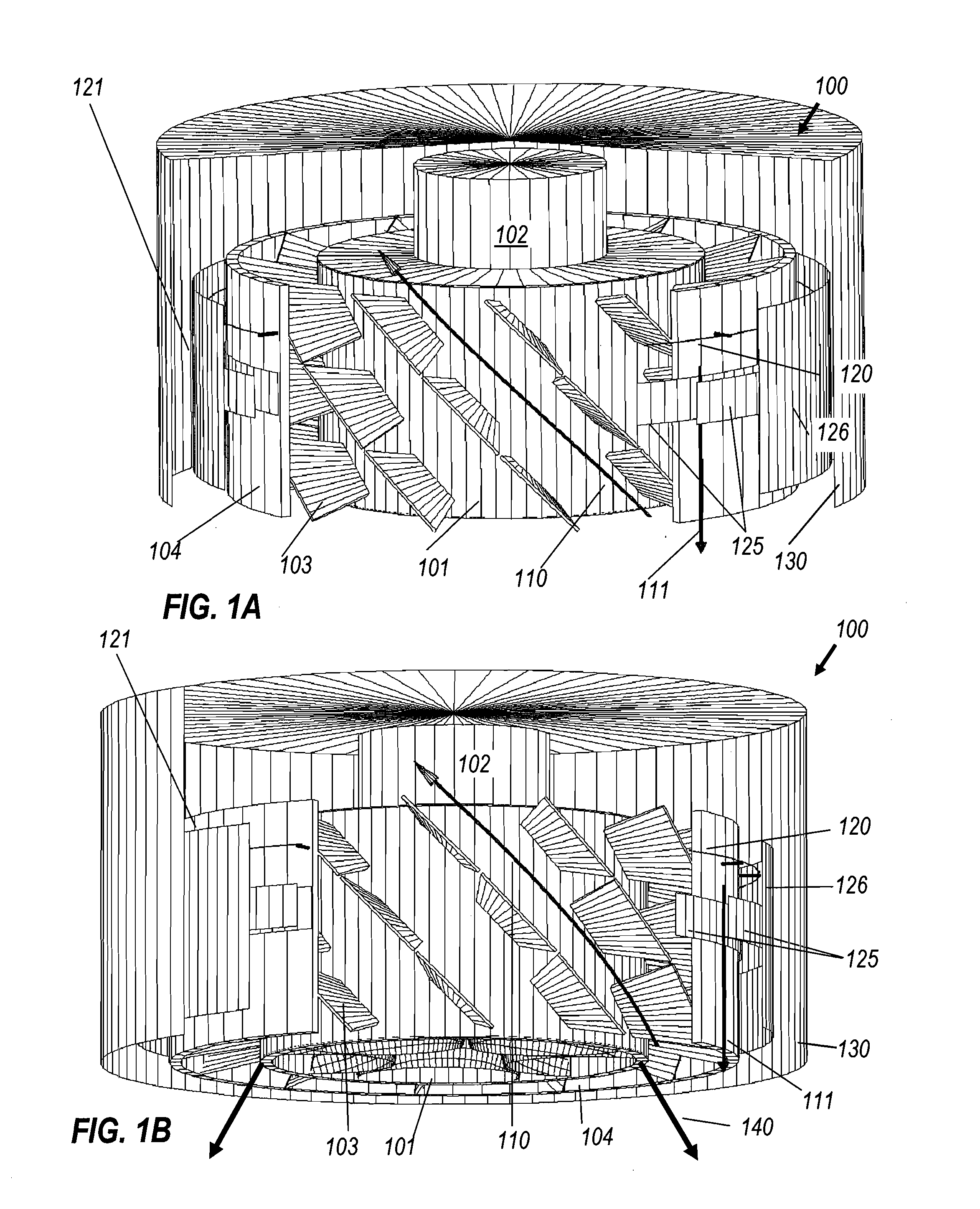
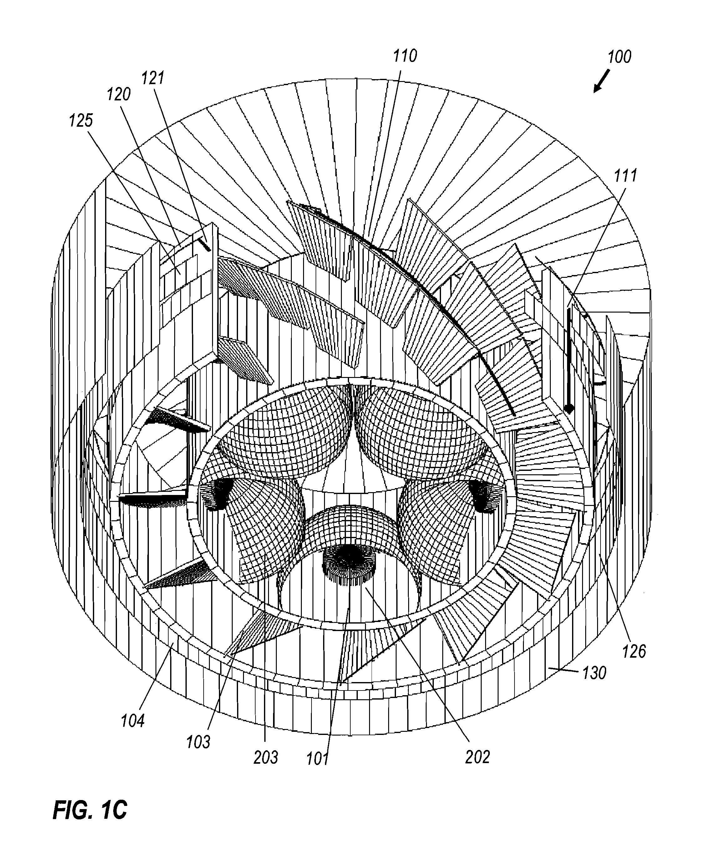
[0023]FIG. 1A (which together with FIG. 1B and FIG. 1C may be collectively referred to as FIG. 1) shows a perspective cutaway view from above of LED downlight 100, comprising an inner sleeve that constitutes the wall of a central optical can 101. LEDs 202 and reflectors 203 (see FIG. 1C) are mounted to the inside walls of optical can 101. Downlight 100 further comprises power supply 102, vanes or fins 103, outer sleeve 104, and an outermost sleeve or shroud 126 outside outer sleeve 104, and is positioned within ceiling can 130. As shown in FIG. 1, there are three tiers of vanes 103. The individual vanes are tilted relative to the axial and circumferential directions of the can 101 and sleeves 104, ...


PUM


Abstract

A heat sink for an LED downlight utilizes tilted fins forming helical air passages that can enhance thermal performance by 30% over conventional fins. To overcome the thermal challenge of installation within the stagnant hot air of insulated ceiling cans, a heat sink has an integral electrostatic air pump on its exterior, to move hot air downwards and drain the stagnant air from the can by establishing a chimney-like circulation up through the heat sink and back down around the outside of the heat sink. The air mover can be powered by a compact high-voltage, low-current power supply similar to those of neon signs. An embodiment of the heat sink is also revealed that is suitable for cooling an LED replacement for standard screw-in or equivalent light bulbs. This device can perform well in variety of orientations (horizontal, vertical, etc.) and fixtures.

Description

CROSS REFERENCE TO RELATED APPLICATIONS[0001]This application claims benefit of U.S. Provisional Patent Application No. 61 / 205,390 by Falicoff and Sun, filed Jan. 16, 2009.[0002]This application makes reference to U.S. patent application Ser. No. 12 / 456,392 (published on Dec. 31, 2009 as US 2009-0323338 A1) and the corresponding International Patent Application No. PCT / U.S.09 / 03593, both filed Jun. 15, 2009, titled “Multi-Reflector Cylindrical Light Source with Interior LEDs and Exterior Heat Sink”, which are incorporated herein by reference in their entirety.BACKGROUND OF THE INVENTION[0003]Heat sinks of the prior art use a variety of fin shapes for natural convection of heat to a cooling fluid, typically ambient air. The air passages formed by the fins are usually either rectangular or cylindrical, although there are also heat sinks with pins instead of fins. Finite-element computation packages can accurately predict thermal performance for heat sinks in a far wider variety of con...

Claims


Application Information

Patent Timeline
Patent Type & Authority Applications(United States)
IPC IPC(8): H01J61/52F28F7/00
CPCF21K9/00F21S8/02F21V29/02F21Y2101/02H01L23/367F21V29/677F21V29/745F21V29/74F21V29/006F21V29/402H01L2924/0002H01L2924/00F21Y2115/10F21V29/51F21V29/63
Inventor FALICOFF, WAQIDISUN, YUPINPARKYN, WILLIAM A.
Owner LIGHT PRESCRIPTIONS INNOVATORS
Why Eureka
Try Eureka