
Magnetic resonance tomography apparatus with a local coil and method to detect the position of the local coil

a technology local coil, which is applied in the field of magnetic resonance tomography apparatus, can solve problems such as problematical coil position determination in magnetic resonance experiments

Inactive Publication Date: 2010-07-22
SIEMENS HEALTHCARE GMBH
View PDF17 Cites 27 Cited by
  • Summary
  • Abstract
  • Description
  • Claims
  • Application Information

AI Technical Summary

Benefits of technology

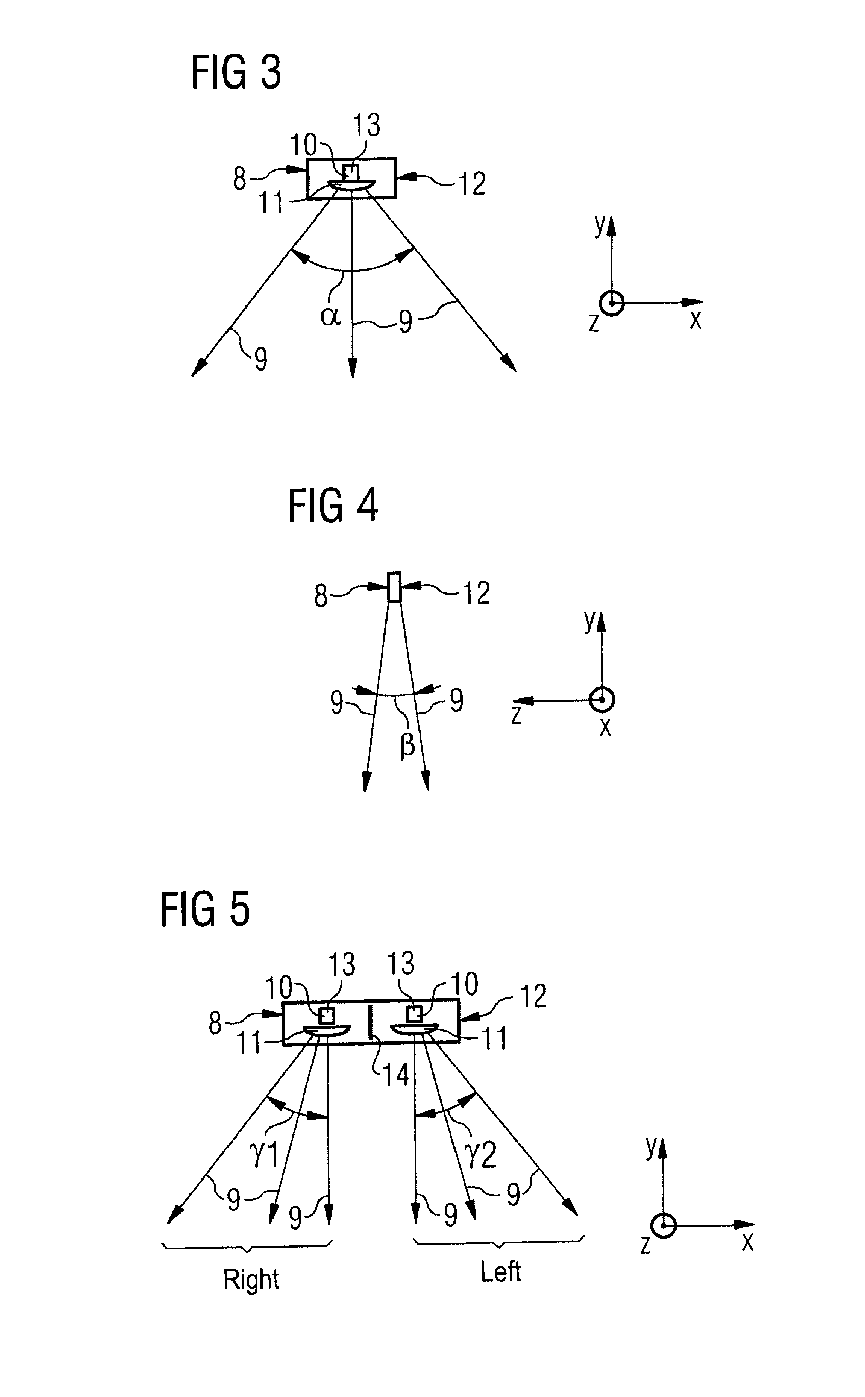
[0016]With regard to the electromagnetic waves that are used, it has proven to be particularly advantageous for the detector system to be fashioned to process electromagnetic waves that propagate optically or quasi-optically. This enables the realization of a relatively precise beam direction or a beam path with which the detection can be implemented with the required precision. Light waves are advantageously used.
[0020]According to a preferred exemplary embodiment of the invention, the reflection device has an encoding structure in order to encode the position of the local coil and / or an orientation of the local coil and / or a type of local coil in the reflected waves. This allows every individual local coil to be precisely identified in an optical manner or, respectively, its position and / or its bearing to be precisely detected.
[0028]Especially if a retroreflector is to be attached to the surface of the local coil, it is advantageous if a reflector foil is used. This is mechanically flexible and therefore can be easily adapted to the different curvatures of the local coil (which is ultimately defined by the body shape of the respective patient). Such reflector foils possess retroreflective pigments (for example transparent plastic balls) on their surface.
[0033]In order to be able to process the signals received from the receiver device, the detector system has an evaluation device that is coupled with the receiver device and that is fashioned to evaluate the receiver signals with regard to the position of the local coil. The receiver signals thereby represent the electromagnetic waves received with the aid of the receiver device. In the case of the image detection and processing device—which can have on the receiver side a camera that can process visible or infrared light, for example—the evaluation device, downstream from the camera, has a device for image processing, a device for pattern recognition and—based on the pattern recognition—a device for coil type detection. This arrangement allows the coil position or the coil orientation to be precisely determined in addition to the detection of the coil type. The basis of this evaluation principle is thus an image of the patient with the local coils placed on him, generated with the use of a camera.
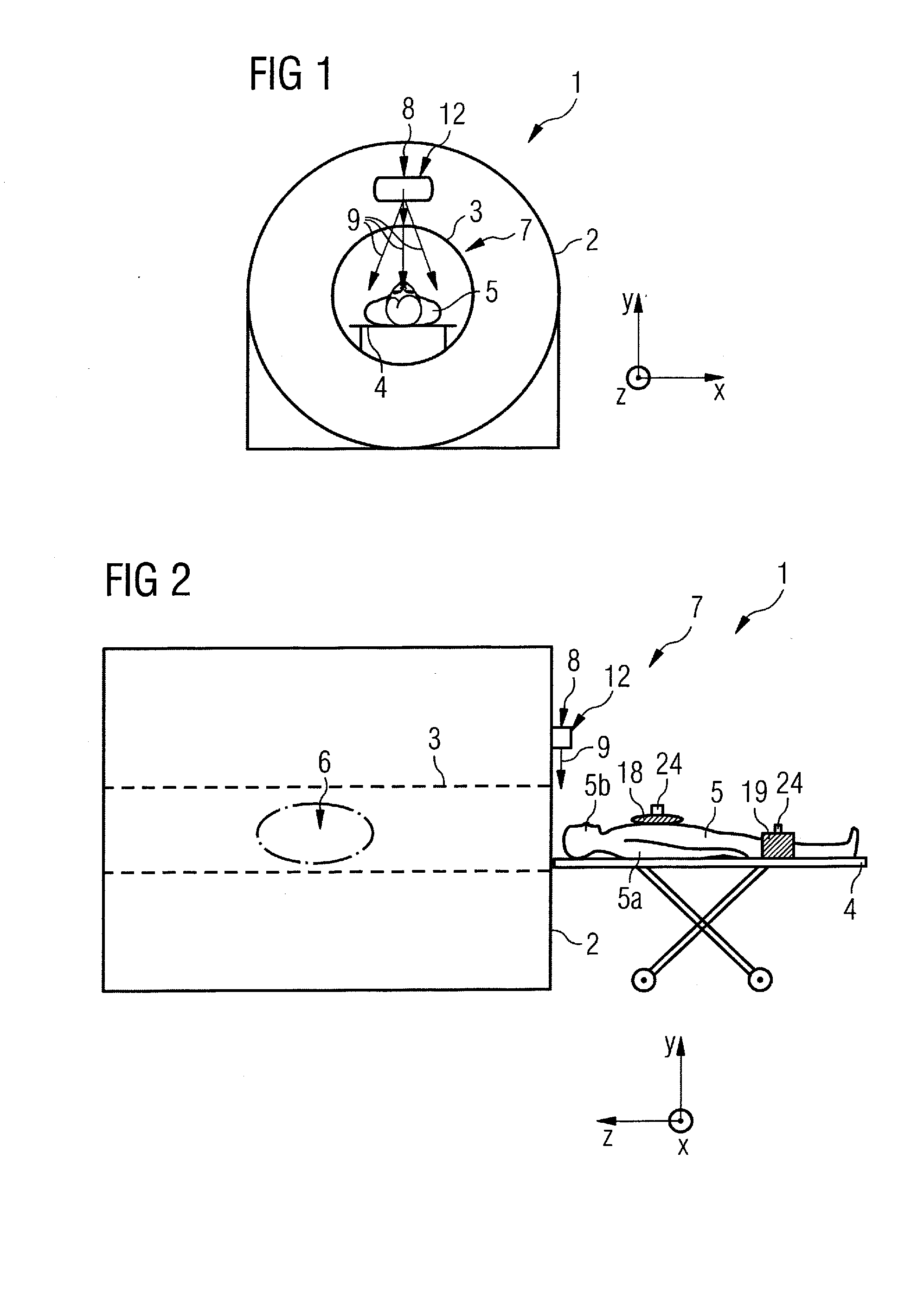
[0038]In an additional configuration, a signal source device and a receiver device—thus both together—are provided at or integrated in the scanner, and a reflection device is installed on or in the local coil. This configuration is advantageous insofar as that no additional signal lines are necessary between the evaluation device (which preferably is also arranged within the magnetic resonance tomography device) and the local coil. The modifications to the local coil are in the present case limited to the attachment of a reflection device on the surface of the local coil.

Problems solved by technology

Additionally, such coil position determinations with magnetic resonance experiments are problematical if the coil to be localized is located outside or at the edge of the homogeneity volume.

Method used


Image

  • Magnetic resonance tomography apparatus with a local coil and method to detect the position of the local coil
  • Magnetic resonance tomography apparatus with a local coil and method to detect the position of the local coil
  • Magnetic resonance tomography apparatus with a local coil and method to detect the position of the local coil

Examples


Embodiment Construction

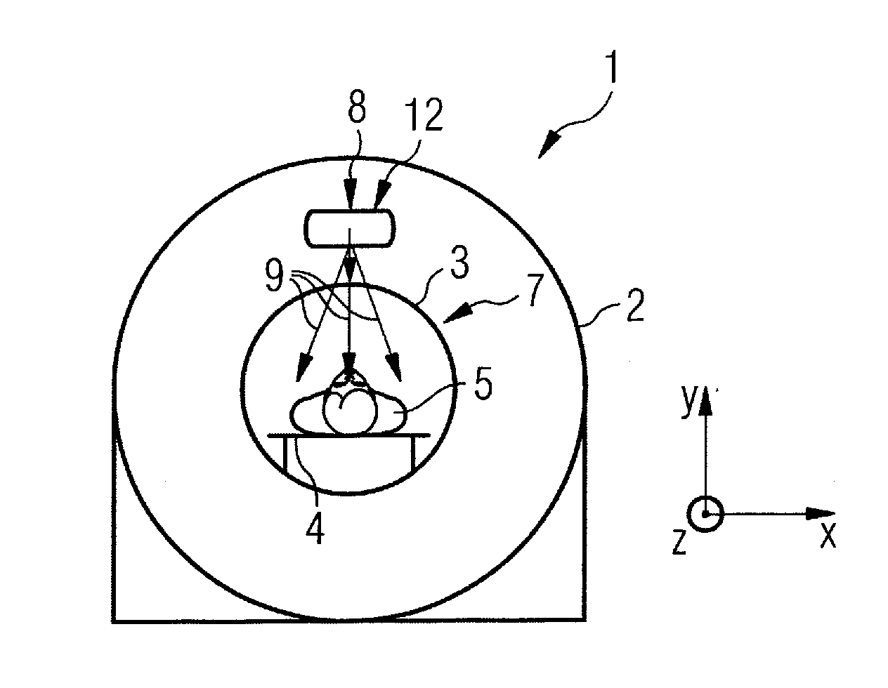
[0063]A magnetic resonance tomography device 1 (abbreviated in the following as an MRT device 1) according to a first exemplary embodiment of the invention is shown in FIG. 1, wherein only those components which are absolutely necessary to describe the invention are shown in detail. For the purpose of orientation, the coordinate system is also depicted with the x-direction, y-direction and z-direction.

[0064]The MRT device 1 possesses a scanner or, respectively, scanner 2 which houses the stationary magnet system and the RF transmission system of the MRT device 1. The scanner 2 possesses a measurement space 3 that is also known as a “bore” in the tech jargon. A bed 4 on which a patient 5 is positioned can be inserted into this measurement space 3 in order to acquire raw data in the known manner within the MRT device 1, wherein electromagnetic waves are generated in the form of a magnetic resonance signal. Volume image data are then later reconstructed in the typical manner from these...


PUM


Abstract

A magnetic resonance tomography device has a local coil that is fashioned to receive a magnetic resonance signal. This device has a detector system that is fashioned to detect a position of the local coil on the basis of electromagnetic waves that are affected by the position of the local coil and can be differentiated from the magnetic resonance signal. A method to detect a position of a local coil in a magnetic resonance tomography device Is implemented in this manner as well.

Description

BACKGROUND OF THE INVENTION[0001]1. Field of the Invention[0002]The invention concerns a magnetic resonance tomography apparatus with a local coil that is fashioned to receive a magnetic resonance signal, and with a detector system that is fashioned to detect a position of the local coil. Moreover, the invention concerns a method to detect a position of a local coil in a magnetic resonance tomography device, the local coil being fashioned to receive a magnetic resonance signal.[0003]2. Description of the Prior Art[0004]Magnetic resonance tomography is a technique in widespread use for the acquisition of images of the inside of the body of a living examination subject. In order to acquire an image with this method, i.e. to generate a magnetic resonance exposure of an examination subject, the body or a body part of the patient that is to be examined must initially be exposed to an optimally homogeneous, static basic magnetic field that is generated by a basic field magnet of the magne...

Claims


Application Information

Patent Timeline
Patent Type & Authority Applications(United States)
IPC IPC(8): G01R33/44
CPCG01R33/341A61B5/064
Inventor BIBER, STEPHAN
Owner SIEMENS HEALTHCARE GMBH
Learn More