Eureka AIR delivers breakthrough ideas for toughest innovation challenges, trusted by R&D personnel around the world.

Optical device with means of actuating a compact deformable membrane

a deformation membrane, optical device technology, applied in optics, instruments, lenses, etc., can solve the problems of bulky and complex mechanical structures associated with the membrane, too expensive for this type of application, and complicated type of actuation,

Active Publication Date: 2010-07-22
WEBSTER CAPITAL LLC
View PDF7 Cites 77 Cited by
  • Summary
  • Abstract
  • Description
  • Claims
  • Application Information

AI Technical Summary

Benefits of technology

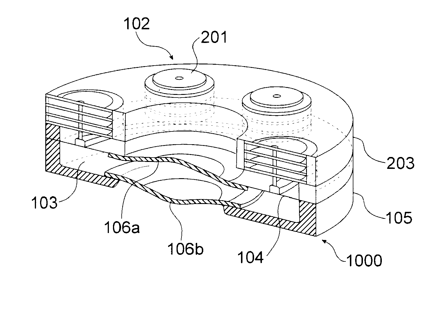
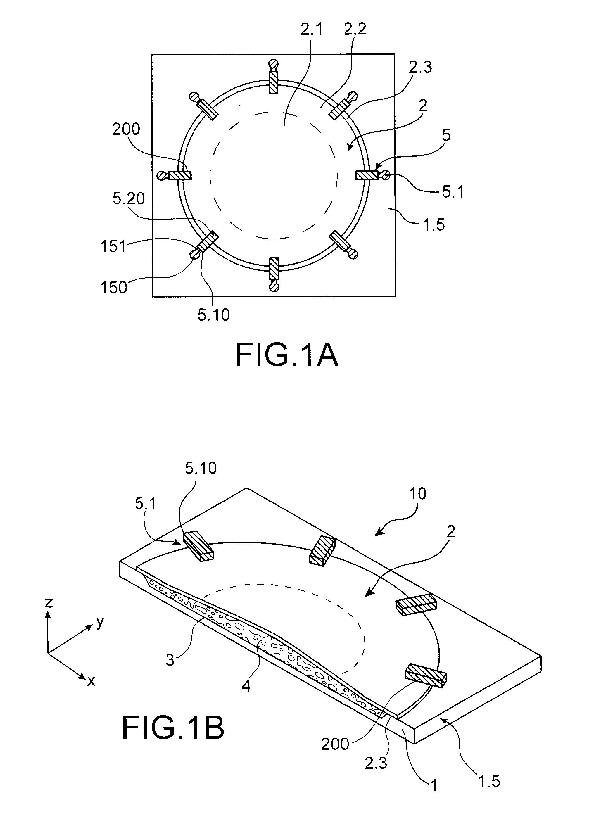
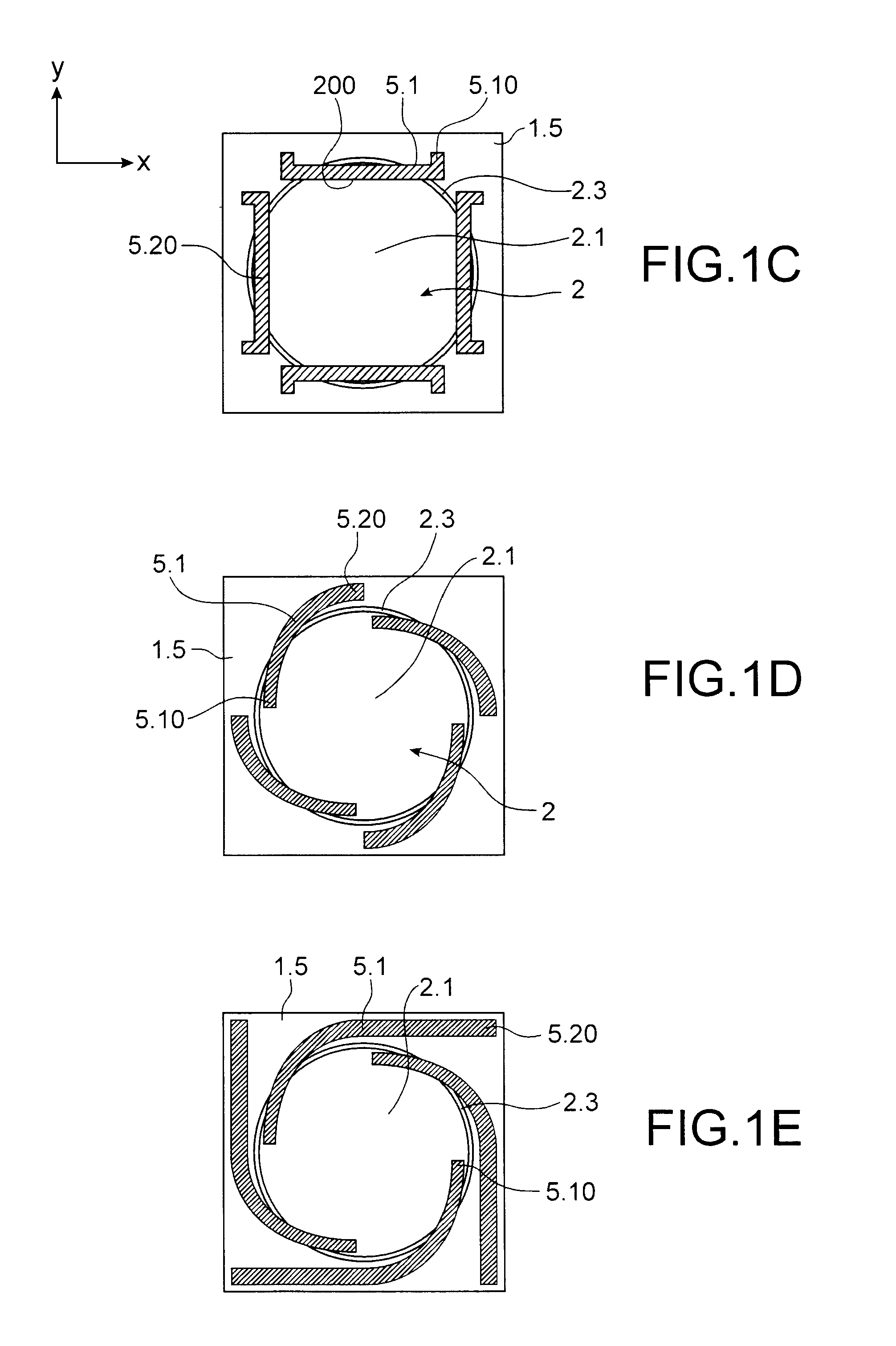
[0018]To achieve this aim, the present invention proposes that the actuation means comprise several thermal or piezoelectric actuators of micro-beam type distributed at the periphery of the membrane, which is simple and reduces the size of the actuation means in a very significant manner.
[0029]The micro-beams may be rectilinear or curved, the latter case making it possible to reduce the surface of the support while increasing the length of the micro-beam. This alternative is also favourable to the reduction of the size.
[0031]The membrane comprises at least one continuous layer occupying the whole surface of the membrane, the risks of leaks are thus reduced.
[0034]In the same way, the reinforced area may extend up to the anchoring area without encroaching upon it or stop before the anchoring area.

Problems solved by technology

In fact, the mechanical structures associated with the membranes are all very complex and are much too expensive for this type of application.
An important drawback is linked to the type of actuation, which is bulky and complex, particularly due to the container.
In addition, the sealings to be carried out are not all situated in a same plane, which leads to awkward manipulations of films or plates, considerably complicating the method employed and the necessary tooling.
These techniques are not compatible with the conventional batch production methods employed to make microelectromechanical systems MEMS or microoptoelectromechanical system MOEMS.
Consequently, their cost remains high, as does their size.
In addition, it is difficult to position the transparent elastic film on the peripheral elastic film during the assembly and to position the ring perfectly during its transfer onto the peripheral elastic film.
Another difficulty is positioning the actuators perfectly in relation to the ring.
If the positioning is not perfect, optical aberrations result, which degrade the quality of the image obtained.
If not, optical aberrations arise and they degrade the quality of the image obtained.
It is very difficult to obtain these results with the recommended multiple sealings.
Furthermore, since several films are hermetically sealed together, in the manner of a patchwork, and to the container to encapsulate the liquid, the risk of leaks is not negligible.

Method used


Image

  • Optical device with means of actuating a compact deformable membrane
  • Optical device with means of actuating a compact deformable membrane
  • Optical device with means of actuating a compact deformable membrane

Examples


Embodiment Construction

[0017]The present invention has precisely the aim of providing an optical device with deformable membrane such as a liquid lens or a mirror that does not have the above mentioned drawbacks, namely the complexity of the actuation means and their size, optical aberrations, the high risk of leaks, the incompatibility with the micro-electronic environment, the impossibility of being produced in batches.

[0018]To achieve this aim, the present invention proposes that the actuation means comprise several thermal or piezoelectric actuators of micro-beam type distributed at the periphery of the membrane, which is simple and reduces the size of the actuation means in a very significant manner.

[0019]Micro-beam is taken to mean an object in which the characteristic dimensions of its section, in other words its thickness and its width, are less than its length. A factor of at least two and ideally greater than five exists between the length and the characteristic dimensions of the section. The or...


PUM


Abstract

An optical device with a deformable membrane including an anchoring area on a support helping to contain a constant volume of liquid in contact with one of its faces, a substantially central area, configured to be deformed reversibly from a rest position, and an actuation mechanism displacing the liquid in the central area, stressing the membrane in parts situated between the central area and the anchoring area. The actuation mechanism includes plural thermal or piezoelectric actuators of micro-beam type, distributed at the periphery of the membrane, the micro-beams including at least one fixed part joined to the support and at least one moving part coming into contact, on an actuation, with the membrane in an area situated between the central area and the anchoring area.

Description

TECHNICAL FIELD[0001]The present invention relates to an optical device with deformable membrane such as a variable focal distance liquid lens, a liquid lens with correction of optical aberrations in adaptive optics or even a membrane deformable mirror.[0002]Among all the types of variable focal distance liquid lenses, there exists one formed of an optical liquid working at constant volume between walls, at least one of which may be displaced. Optical liquid is taken to mean a liquid that has optical properties appropriate to the refraction of light and which has an index greater than 1, typically 1.4 or 1.5. Hereafter, the term liquid will simply be used. However, lenses of this type are hardly used in miniature cameras such as those integrated in camera-telephones because the mechanical structures for varying their focal distance are complex, they penalise the size, the cost and the reliability of these lenses.[0003]These miniature cameras, working in the visible, are known as CCM...

Claims


Application Information

Patent Timeline
IPC IPC(8): G02B3/14
CPCG02B3/14G02B26/0866G02B26/0858G02B26/0825
Inventor BOLIS, SEBASTIEN
Owner WEBSTER CAPITAL LLC
Why Eureka
Eureka Blog
Learn More