Check patentability & draft patents in minutes with Patsnap Eureka AI!

Powered hand truck

a hand truck and power technology, applied in the field of small portable, powered lifting and transport devices, can solve the problems of inability to articulate and inconvenient operation of forklift type vehicles, and achieve the effect of great maneuverability and versatility

Active Publication Date: 2010-07-22
BORNTRAGER STEVEN +1
View PDF30 Cites 30 Cited by
  • Summary
  • Abstract
  • Description
  • Claims
  • Application Information

AI Technical Summary

Benefits of technology

[0010]A support column for the lift mechanism is pivotally mounted above the center of the axle and allows the lift mechanism to pivot left or right relative to the longitudinal axis of the chassis for greater maneuverability and versatility. The lift mechanism comprises upper and lower pairs of parallel arms extending from the support column, with the distal ends of the arms attaching to a fork lift mast, which remains parallel to the lift mechanism support column at all times. This arrangement results in the forks being carried close to the two support wheels and tires when the forks are close to the surface, with the forks and arms swinging upwardly and outwardly away from the chassis as the arms rise to a horizontal orientation. The forks move back closer to the vehicle as the arms continue to rise, thereby moving the center of gravity of the load closer to the vehicle when the load is lifted to a relatively great height. The forks are raised by a hydraulic cylinder, which extends between the lower set of arms and the upper end of the forklift mast. A forklift mast extension winch is provided at the top of the mast to raise the upper portion of the mast and its lateral brace as required during certain operations.

Problems solved by technology

However, such forklift type vehicles are not suitable for use in the operating environment of the present invention due to their relatively bulky configuration, wheel configuration, etc.
The controls are deployed from a fixed location on the machine and cannot articulate to suit the location or position of the operator.

Method used


Image

  • Powered hand truck
  • Powered hand truck
  • Powered hand truck

Examples


Embodiment Construction

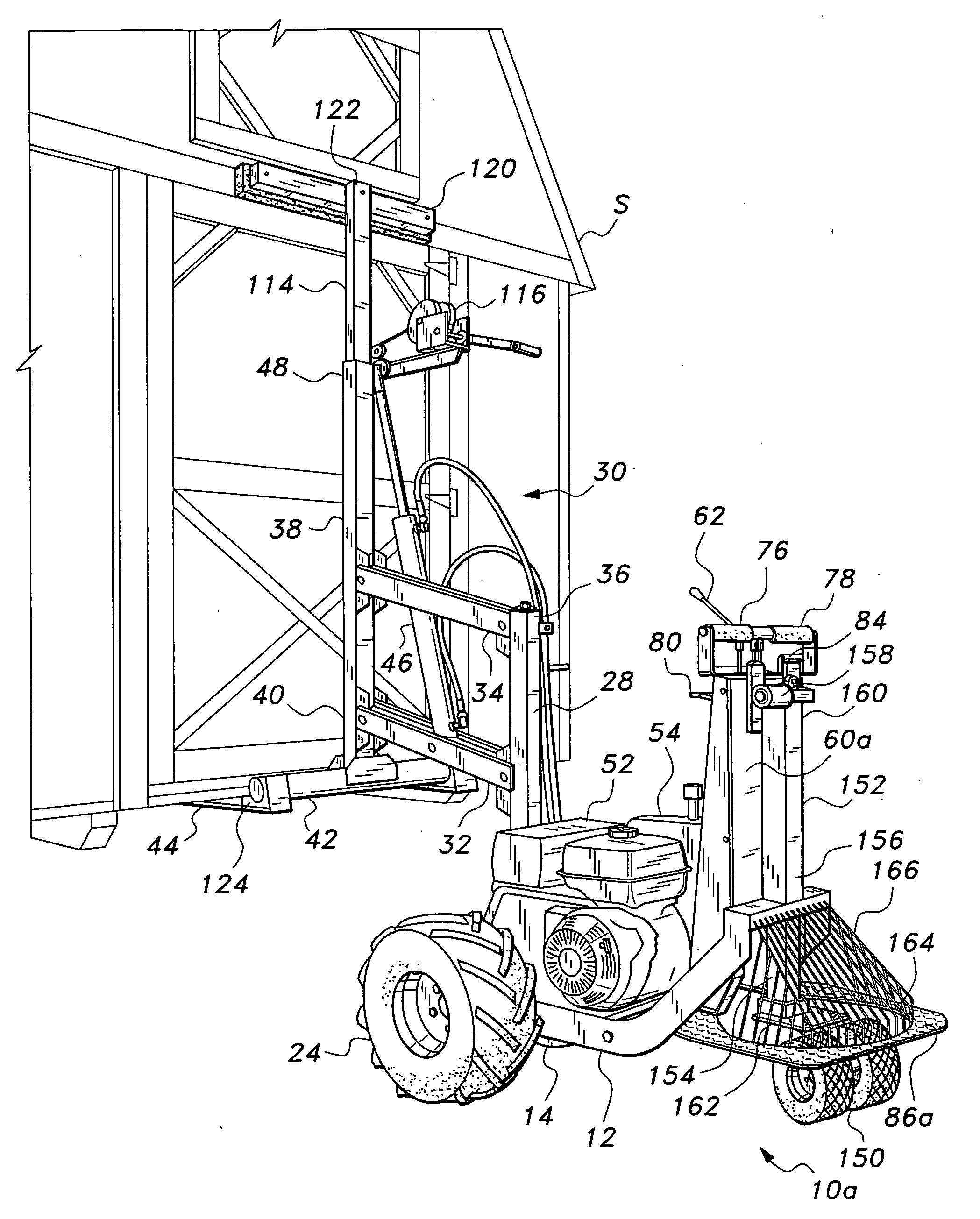
[0036]The present invention comprises a powered hand truck for the movement of relatively large and heavy objects (e.g., skid mounted portable buildings, dumpsters, etc.) over relatively short distances. A portable storage rack for mounting upon a transport vehicle (e.g., flat bed pickup truck, etc.) is also provided for the transport of the powered hand truck, as required.

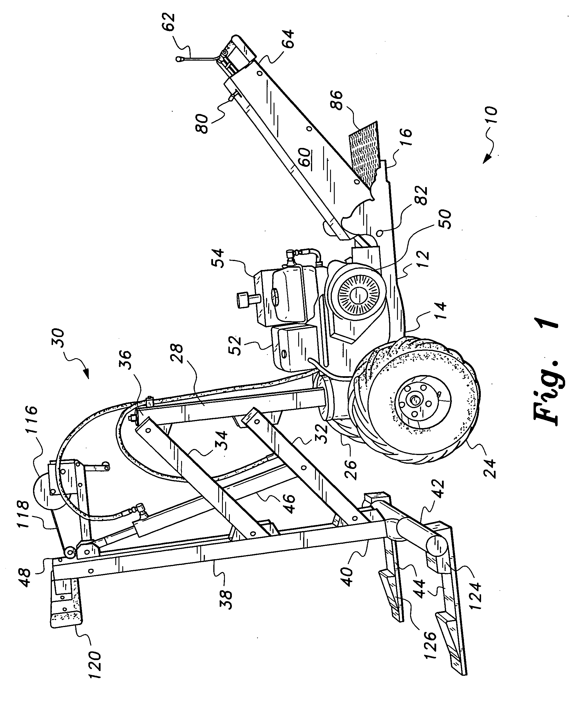
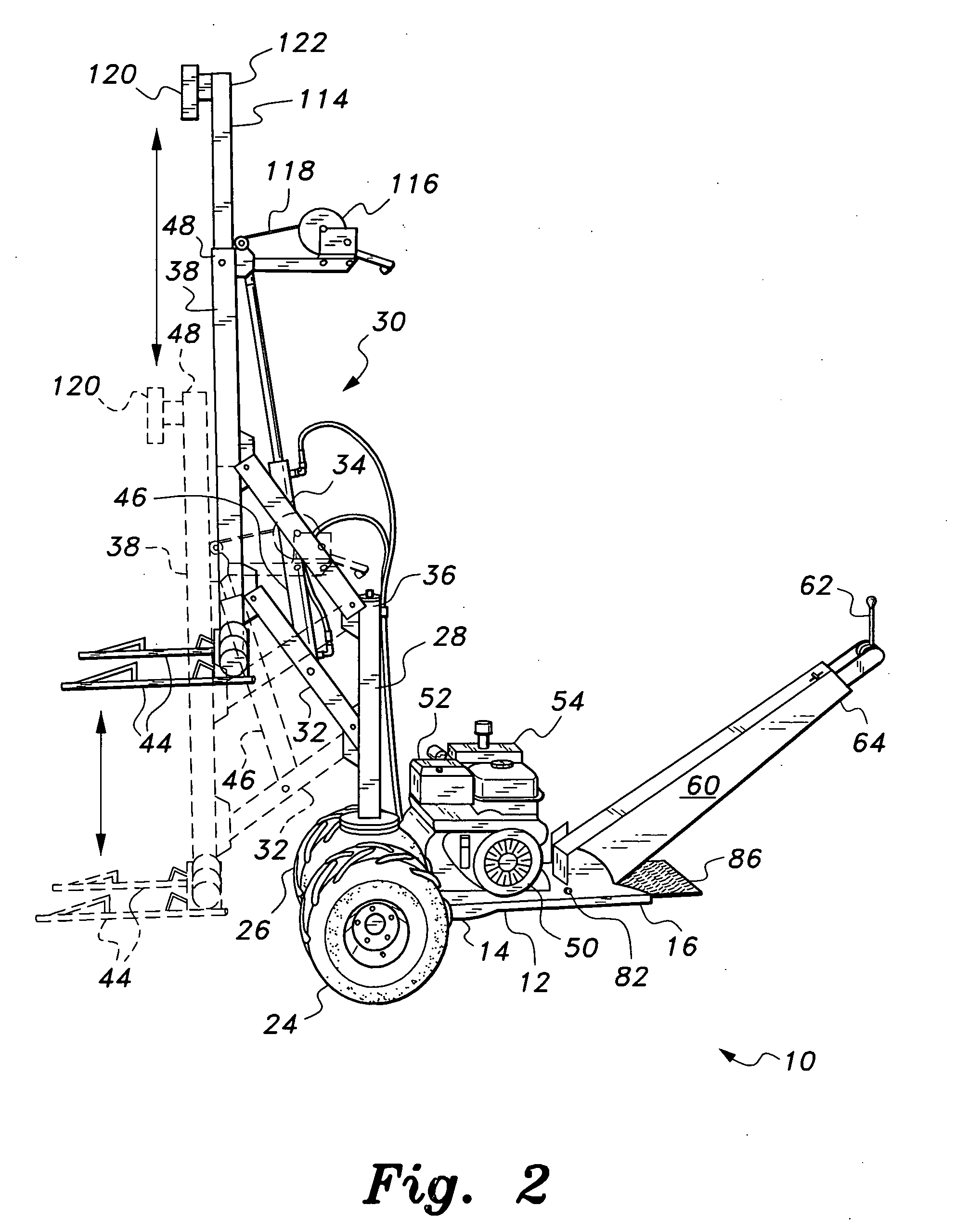
[0037]FIG. 1 of the drawings provides a left side perspective view of the powered hand truck 10, illustrating its general features. The hand truck 10 includes a chassis 12 having a support axle end 14 and an opposite operator end 16. A single axle 18 (shown most clearly in FIG. 4) extends laterally across the support axle end 14 of the chassis 12, with the remainder of the chassis (including the operator end 16) being cantilevered from the single support axle 18. The axle 18 has opposite first and second ends, respectively 20 and 22, with first and second drive wheels, respectively 24 and 26, installed upon the fi...


PUM


Abstract

The powered hand truck has a chassis supported at one end by a single axle with two independently operable drive wheels. A prime mover is provided generally medially on the chassis, driving the drive wheels and powering the forklift mechanism. An operator console extends from the end of the chassis opposite the wheels, with an operator platform extending beyond the base of the operator console. The forklift mechanism has a pantograph arrangement supported by a pivotally mounted column. The forklift mast remains parallel to the column at all times and includes a manually or power actuated upper extension. A storage rack and dolly may be installed upon a suitable transport vehicle for transporting the powered hand truck. The hand truck forks engage the storage rack dolly, with the dolly translating along the rack to allow the truck to be deployed from, or loaded onto, the transport vehicle.

Description

REFERENCE TO RELATED PATENT APPLICATIONS[0001]This application is a continuation-in-part of U.S. patent application Ser. No. 12 / 285,244, filed on Sep. 30, 2008, which is a division of U.S. patent application Ser. No. 11 / 822,844 filed on Jul. 10, 2007, now issued as U.S. Pat. No. 7,597,522 on Oct. 6, 2009, which claimed the benefit of U.S. Provisional Patent Application Ser. No. 60 / 838,138, filed on Aug. 17, 2006.BACKGROUND OF THE INVENTION[0002]1. Field of the Invention[0003]The present invention relates generally to small, portable, powered lifting and transport devices. More particularly, the present invention comprises a powered hand truck having a self-contained prime mover on board, which powers a hydraulic system for driving the wheels and lifting mechanism of the device.[0004]2. Description of the Related Art[0005]A number of powered devices comprising a wide array of different configurations have been developed in the past for the powered lifting and carriage of large, bulky...

Claims


Application Information

Patent Timeline
IPC IPC(8): B66F9/06B62D51/04B62D51/02B66F9/075
CPCB62D51/04B66F9/065Y10S414/122Y10S414/13
Inventor BORNTRAGER, STEVENBORNTRAGER, JAMES
Owner BORNTRAGER STEVEN
Features
  • R&D
  • Intellectual Property
  • Life Sciences
  • Materials
  • Tech Scout
  • Unparalleled Data Quality
  • Higher Quality Content
  • 60% Fewer Hallucinations
Learn More