Electric motor

a technology of electric motors and motors, applied in the field of electric motors, can solve the problems of difficult production, difficult to successfully put into production, and inability to use concentrated windings, etc., and achieve the effect of reducing the weight and size of pmdc motors without reducing performance or power, and high power density applications

Active Publication Date: 2010-07-22
JOHNSON ELECTRIC SA
View PDF5 Cites 22 Cited by
  • Summary
  • Abstract
  • Description
  • Claims
  • Application Information

AI Technical Summary

Benefits of technology

[0009]Thus, it is desirable to reduce the weight and size of a PMDC motor without reducing its performance or power. Also it is desirable to achieve this, even for a PMDC motor, having more than four stator poles. Multi-pole motors (i.e. motors with more than four stator poles) are becoming popular as a way to handle high power density applications.
[0010]One preferred way to achieve this is to reduce the axial length of the motor, making the motor more compact, lighter and reducing the amount of wire used, thus saving material cost. One way of doing this is by using a rotor with concentrated windings.
[0011]The present invention aims to reduce the problems associated with known concentrated winding motors by providing a simple winding scheme which gives improved motor performance in a multiple pole PMDC motor.

Problems solved by technology

However, other factors are also affected.
However, this design proves to be difficult to successfully put into production due to the complex slot shapes.
However, for an armature with many rotor poles, concentrated windings are usually not a option especially for miniature and small sized PMDC motors.

Method used


Image

  • Electric motor
  • Electric motor
  • Electric motor

Examples


first embodiment

[0051]Taking FIGS. 3 & 4 as the first example and assuming that brushes B1 and B4 are the positive brushes with brush B1 contacting segment C1 and brush B4 contacting segment C13, and brushes B2 and B3 are the negative brushes with brush B2 contacting segment C4 and brush B3 contacting segment C10, the current paths and the resulting magnetic field are now described.

[0052]The current flows through positive brushes B1, B4 through segments C1, C7, C13 into two parallel paths, one through coils W1 / W7 (W1 and W7 are parallel connected by equalizer E1, E2), W6, W2 / W8 (W2 and W8 are parallel connected by equalizer E3, E4), the other through coils W5, W3 / W9 (W3 and W9 are parallel connected by equalizer E5, E6), W4 through segments C4, C10, C16 to negative brushes B2, B3.

[0053]This creates the following magnetic poles on the rotor. Teeth T3, T6, T9 become North poles, and teeth T1, T2, T4, T5, T7, and T8 become South poles which react with the stator poles to cause the rotor to rotate in C...

second embodiment

[0067]Looking now at FIGS. 5 & 6 as the second example and assuming that brushes B1 and B3 are the positive brushes with brush B1 contacting segment C1 and brush B3 contacting segment C13, and brushes B2 and B4 are the negative brushes with brush B2 contacting segment C4 and brush B4 contacting segment C16, the current paths and the resulting magnetic fields are now described.

[0068]The current flows through positive brushes B1, B3 through segments C1, C7, C13, C19 into four parallel paths, one through coils W1, W6, W5, another through coils W7, W12, W11, a third through coils W2, W9, W10, and the fourth through coils W8, W3, W4 through segments C4, C10, C16, C22 to negative brushes B2, B4.

[0069]This creates the following magnetic poles on the rotor. Teeth T3, T6, T9, and T12 become North poles, and teeth T1, T2, T4, T5, T7, T8, T10, and T11 become South poles which react with the stator poles to cause the rotor to rotate in the CCW direction.

[0070]As the rotor turns the brushes move...


PUM


Abstract

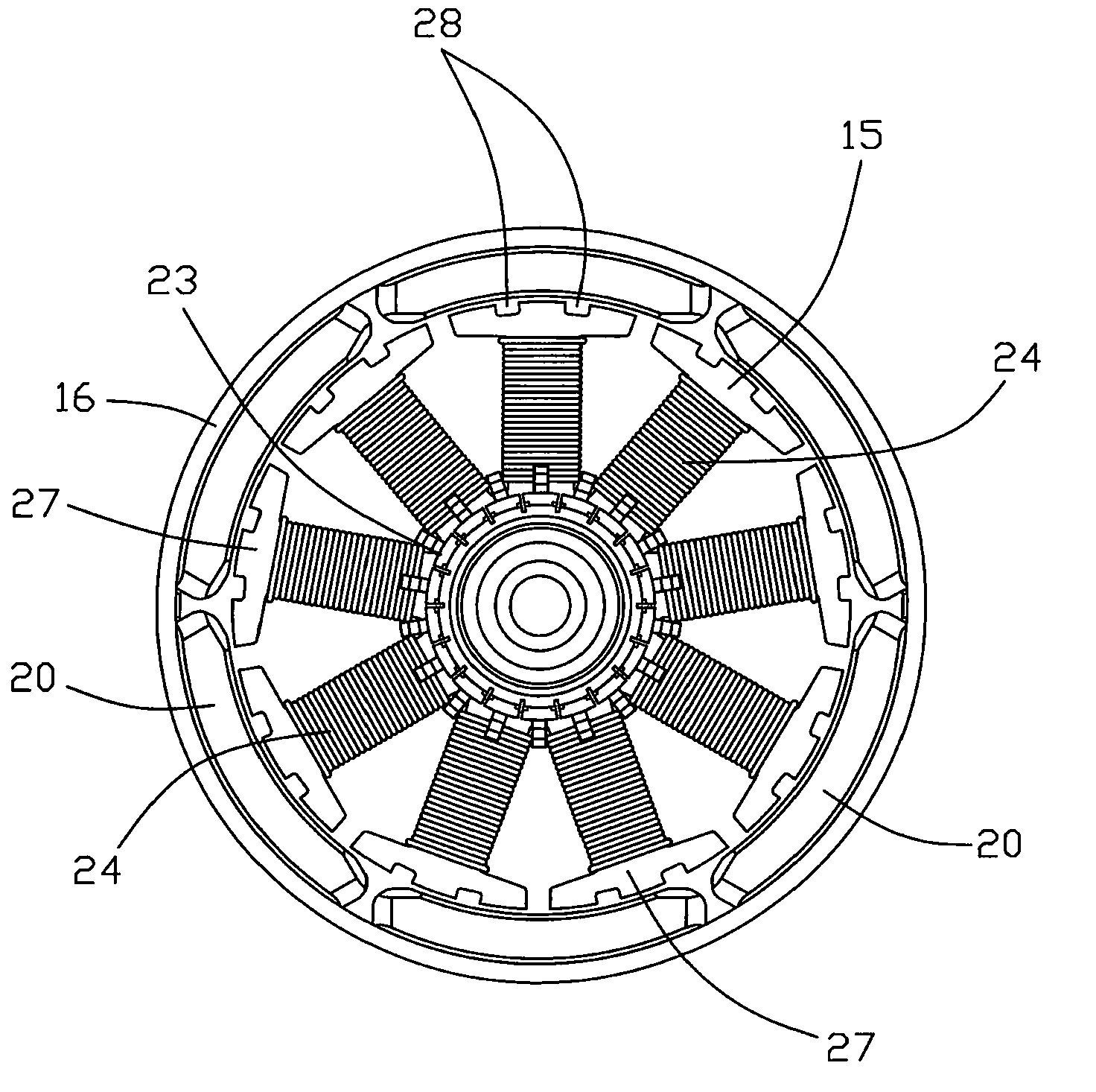
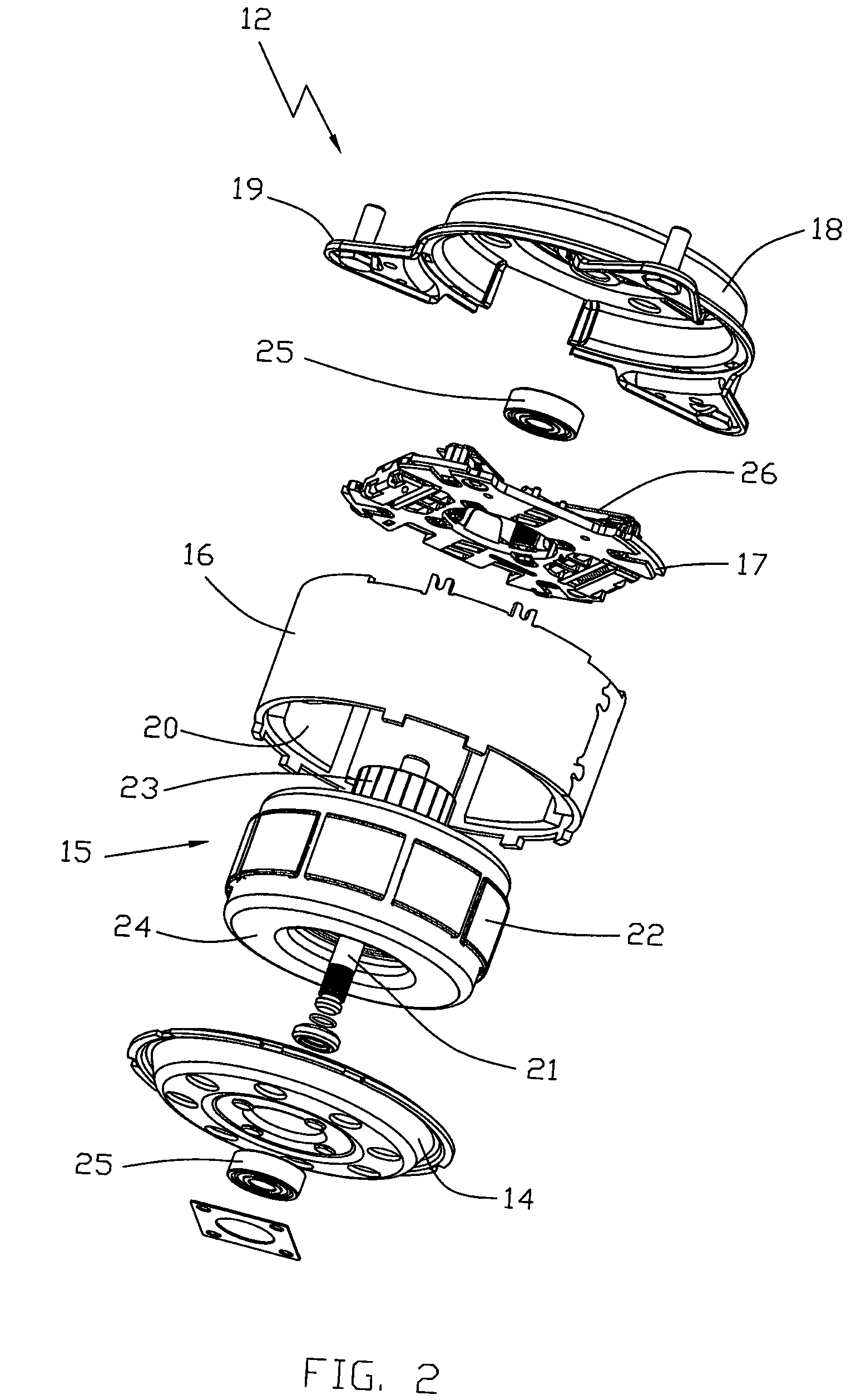
A DC motor 12, has a stator housing 16 accommodating a permanent magnet stator and a rotor 15 rotatably mounted confronting the stator. The rotor 15 has a shaft 21, a rotor core 22 fitted to the shaft and having laminations forming salient poles or teeth 27. A commutator 23 is fitted to the shaft adjacent one end of the rotor core and windings 24 are wound about the teeth and terminated on segments of the commutator 23. The windings is formed by a number of coils with each coil being wound around a single tooth of the rotor and each tooth supporting a single coil. Brush gear comprising a plurality of brushes 26 in sliding contact with the commutator 23, transfers electrical power to the windings.

Description

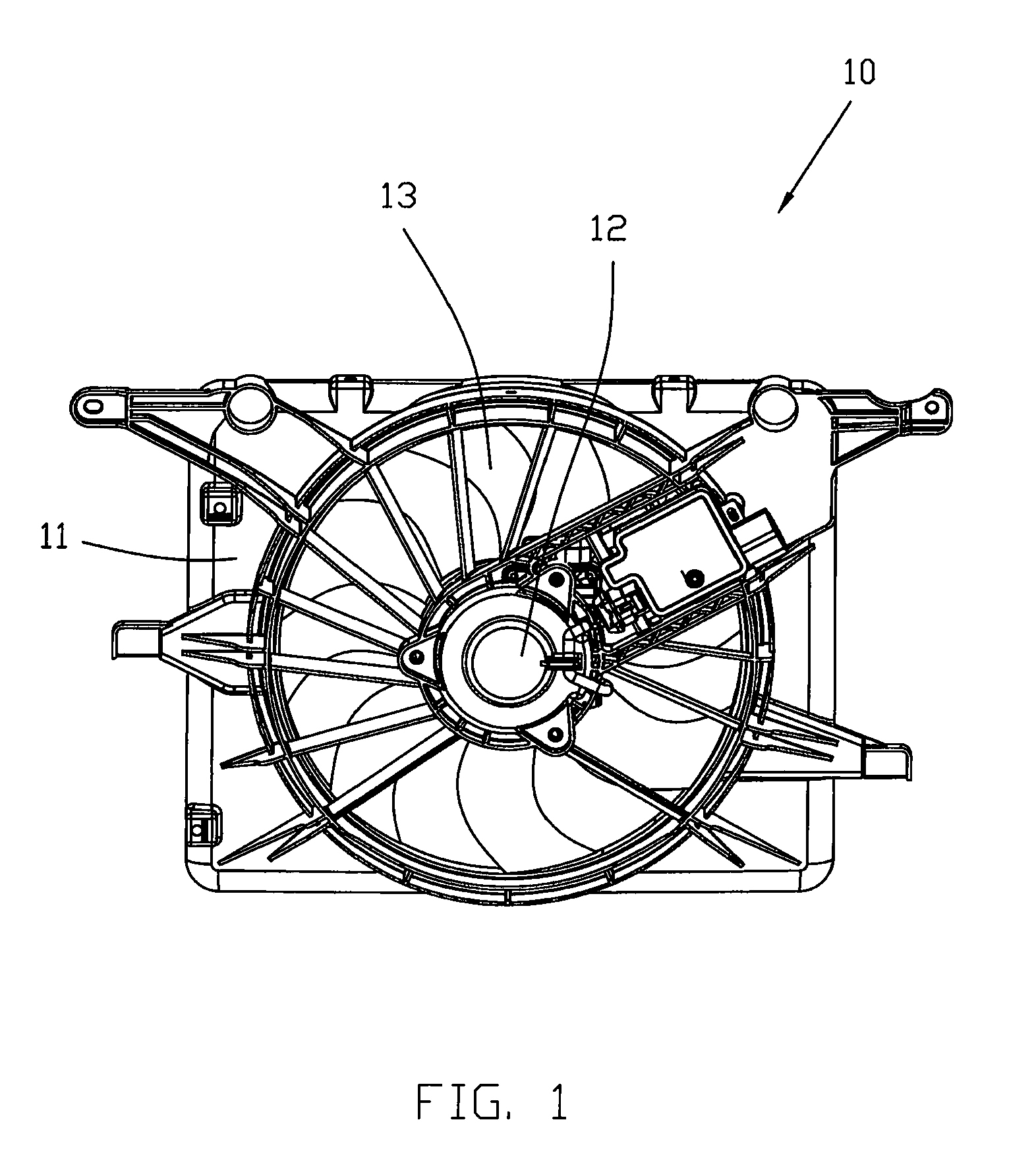
CROSS REFERENCE TO RELATED APPLICATIONS[0001]This non-provisional patent application claims priority under 35 U.S.C. §119(a) from Patent Application No. 200910105141.9 filed in The People's Republic of China on Jan. 19, 2009.FIELD OF THE INVENTION[0002]This invention relates to an electric motor having a wound rotor with a commutator, and in particular, to a multi-pole PMDC motor having a concentrated winding and to a cooling fan module incorporating such a motor. The term ‘multi-pole’ is used here to mean motors having four or more stator poles. The invention has particular application to PMDC motors having six or eight stator poles.BACKGROUND OF THE INVENTION[0003]PMDC motors are well-known and have many uses. The current trend, driven by customer demand, is for smaller, lighter and / or more powerful motors. One such application is for the fan motor of a cooling module for a vehicle engine. Space is always a premium in the modern vehicle engine compartment and weight is a prime tar...

Claims


Application Information

Patent Timeline
Patent Type & Authority Applications(United States)
IPC IPC(8): F04D25/08H02K23/04
CPCH02K23/28H02K23/30
Inventor QIN, RUI FENGYANG, LINGLIU, BAO TINGZHOU, CHANG JIN
Owner JOHNSON ELECTRIC SA
Why Eureka
Try Eureka