

Magnetic carrier, two-component developer and image forming method
a two-component developer and carrier technology, applied in the field of magnetic carrier, two-component developer and image forming method, can solve the problems of weakening the electric field applied to the two-component developer, coarse halftone images, image defects, etc., and achieves good efficiency, high-quality images, and superior development performance.
- Summary
- Abstract
- Description
- Claims
- Application Information
AI Technical Summary
Benefits of technology
Problems solved by technology
Method used
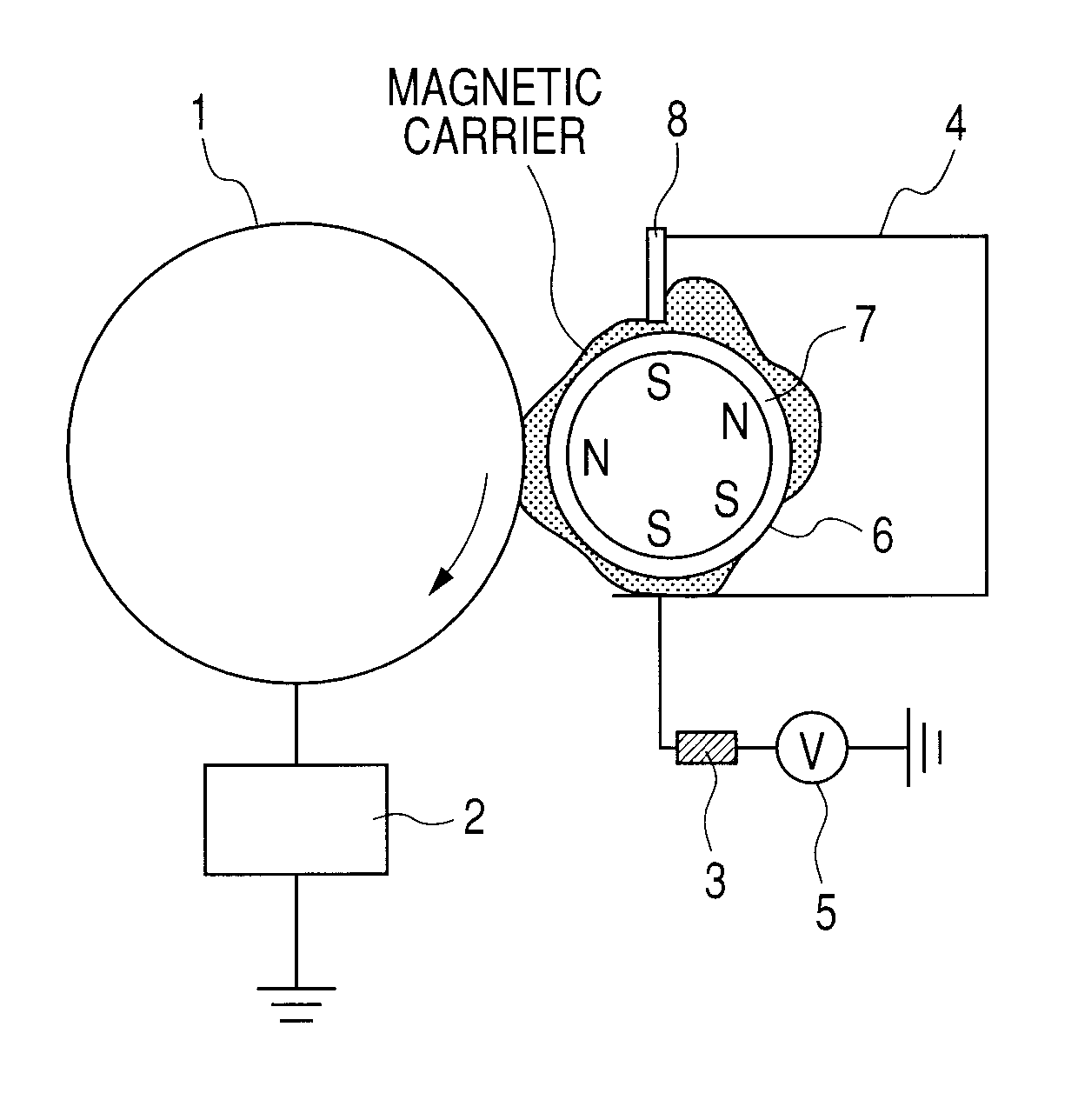
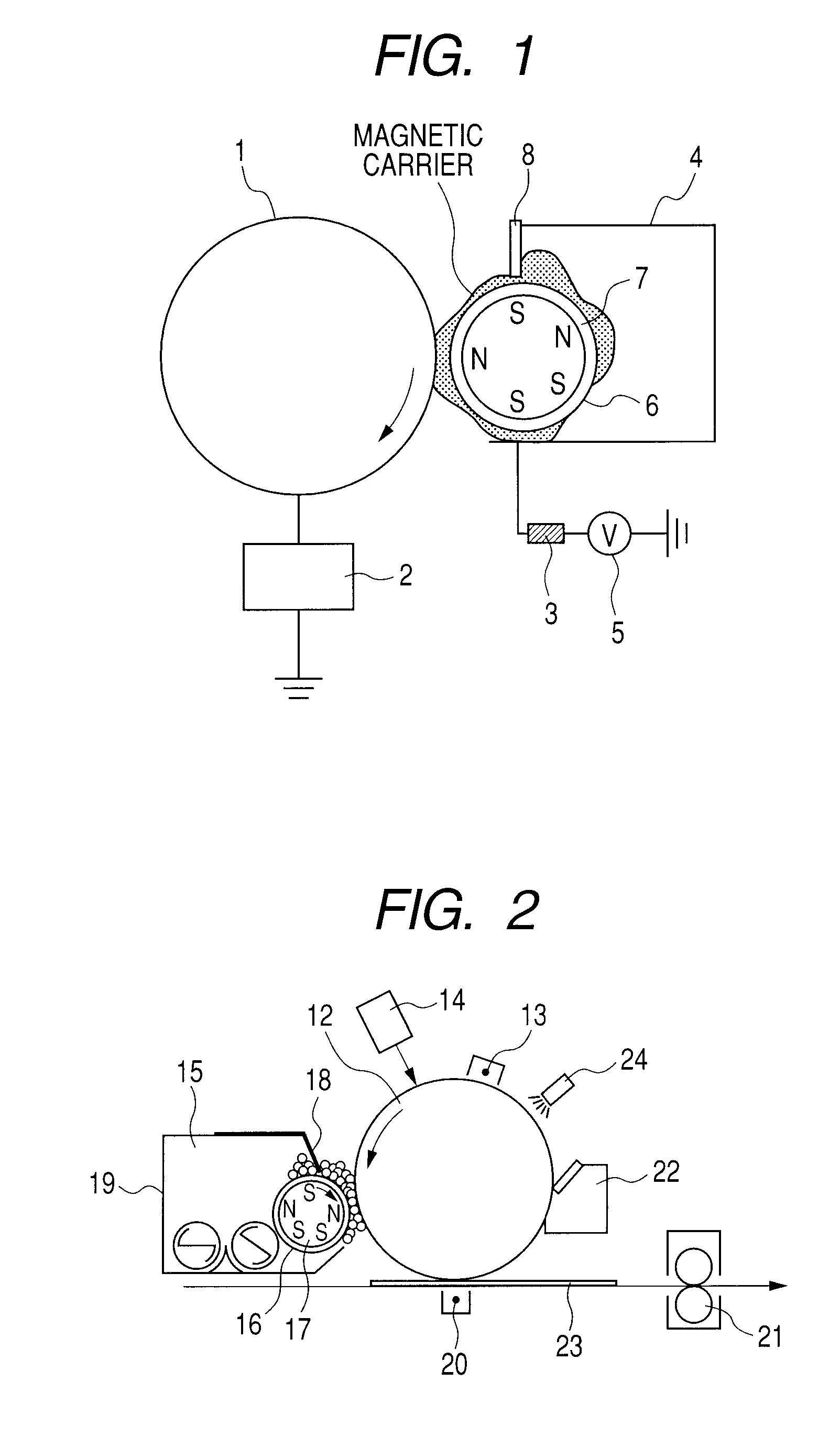
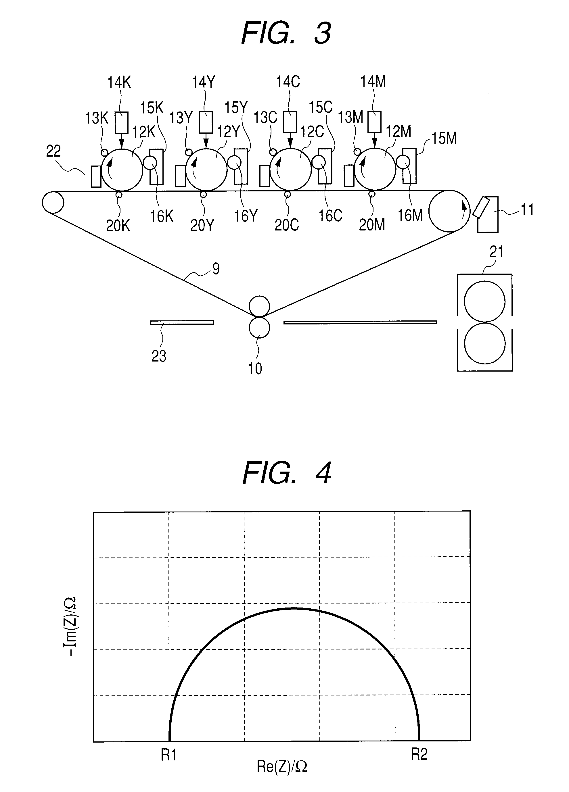
Image

Examples
production example 1
Magnetic Carrier Production Example 1
[0316]
Straight silicone resin20.0% by mass(SR2411, available from Dow Corning ToraySilicone Co., Ltd.; dynamic viscosity in 20% by masstoluene solution: 1.1 × 10⁻⁴ m2 / sec)γ-aminopropylethoxysilane 0.5% by massToluene79.0% by mass
[0317]The above materials were so mixed as to be in the above compositional ratio to obtain Resin Solution 1.
[0318]Step 1 (Resin Filling Step)
[0319]100 parts by mass of Magnetic Core Particles 1 was put into an agitating container of a universal mixing agitator manufactured by Dulton Company Limited. While keeping its temperature at 30° C. and while producing a vacuum, nitrogen was introduced thereinto. Subsequently, Resin Solution 1 was so added as to be in an amount of 10 parts by mass as a resin component, based on the mass of Magnetic Core Particles 1. Then the agitation was continued for 2 hours as it was, and thereafter the temperature was raised to 70° C. to remove the solvent. The material obtained was moved to Ju...
production example 2
Magnetic Carrier Production Example 2
[0322]In Magnetic Carrier Production Example 1, the procedure of Step 1 was repeated to obtain Filled Core Particles 2, except that Magnetic Core Particles 1 was changed for Magnetic Core Particles 2 and the amount of 10 parts by mass for the resin added was changed to 12 parts by mass, and the procedure of Step 2 was repeated to obtain Magnetic Carrier 2, except that Filled Core Particles 2 was used instead. Magnetic Carrier 2 obtained had a 50% particle diameter based on volume distribution (D50) of 40.1 μm.
production example 3
Magnetic Carrier Production Example 3
[0323]In Magnetic Carrier Production Example 1, the procedure of Step 1 was repeated to obtain Filled Core Particles 3, except that Magnetic Core Particles 1 was changed for Magnetic Core Particles 3 and the amount of 10 parts by mass for the resin added was changed to 16 parts by mass, and the procedure of Step 2 was repeated to obtain Magnetic Carrier 3, except that Filled Core Particles 1 was changed for Filled Core Particles 3. Magnetic Carrier 3 obtained had a 50% particle diameter based on volume distribution (D50) of 36.3 μm.
PUM
 Abstract
Description
Claims
Application Information