Systems and methods for the medical treatment of structural tissue

a technology of structural tissue and medical treatment, applied in the field of biomedical devices and methods, can solve the problems of insufficient safety treatment of prior devices, difficulty in insertion, and difficulty in adjusting the position of the spinal cord, so as to increase the purchase, facilitate the insertion, and increase the purchase

Inactive Publication Date: 2010-07-22
GOOCH HUBERT L
View PDF85 Cites 10 Cited by
  • Summary
  • Abstract
  • Description
  • Claims
  • Application Information

AI Technical Summary

Benefits of technology

[0016]In some embodiments, the anchoring mechanism(s) may be constructed to have one or more movable and / or malleable portions such as external wall members that may expand upon insertion of a shaft(s), screw(s), bolt(s), etc., to provide increased purchase, gripping, or attachment between a screw, a holding means and / or an anchoring mechanism(s), and structural tissue. In various embodiments, the anchoring mechanism may have one or more slits along its wall(s) that enable various parts of the anchoring mechanism to expand upon insertion of a shaft(s), screw(s), bolt(s), etc. In any case, either or both the inner and outer surfaces and / or walls of the anchoring mechanism(s) may be tapered, straight, threaded, and / or smooth. An opening in the anchor for insertion of expansion mechanisms (e.g., shaft(s), screw(s), bolt(s), etc.) may be of varying dimensions to accommodate a desired diameter or length of screw. A shaft, screw, bolt, etc. may be inserted into, attached or affixed to the anchoring mechanism(s) so as to expand the anchoring mechanism(s) and may be used to attach one or more instrumentations thereto. For example, a plate may be attached to a bone screw and the bone screw may be inserted into, attached or affixed to the anchoring mechanism. Usually, a screw or bolt may be placed into the bone and then the plate or rod is attached to the screw or bolt. In this manner, the external surface size of the anchoring mechanism(s) with an expansion mechanism such as a shaft(s), screw(s), bolt(s), etc., inserted therein may increase purchase gripping or attachment between the structural tissue (e.g., bone) and the shaft(s), screw(s), bolt(s), etc. and / or anchoring mechanism(s). In various embodiments the anchoring mechanism(s) may provide for reduction of micro-motion of a pedicle or bone screw, that may be caused by the movement of the instrumentation or bone, so as to reduce friction and / or structural tissue wear-out, for example, by including a moveable and / or malleable portion to the anchor mechanism. For example, the movable or malleable portions may act as a shock absorber or pivot point cushion so as to reduce wear and tear of the structural tissue to attachment mechanism interface.
[0026]In at least one embodiment of the anchoring mechanism(s), the anchoring mechanism(s) may include a means for holding or a holder or mechanism(s) to grip the anchoring mechanism(s). The holder or grip may be utilized so as to minimize torsion against the surrounding structural tissue and / or increase placement accuracy. Various embodiments of the anchoring mechanism(s) may include additional structures on the outside of the anchoring mechanism(s) to counter the torsion applied by inserting a screw (bolt, etc.) by, for example, increasing the friction between the anchoring mechanism and structural tissue. For example, the anchoring mechanism(s) may include de-rotational “fins” or studs that may be impacted into structural material, e.g., bone. Further, a clamp means may be used to hold the anchor by friction and / or insertion or inclusion of studs may be place into de-rotational holes around the top of the anchoring mechanism(s).

Problems solved by technology

While many areas of medicine and structural tissue anomalies may present difficulties, some particularly difficult areas may involve orthopedic procedures concerning complex or sensitive areas, e.g., the spinal column.
When considering the spinal column, in addition to damage of the surrounding tissue of the pedicle wall, once a pedicle or bone screw is inserted, damage or irritation to the spinal cord may be a concern if the cortical pedicle wall becomes breached.
Prior devices have inadequately addressed the problem of safely and quickly improving screw purchase or gripping within structural tissue that may be efficiently implanted during a surgical procedure.
These procedures and similar procedures are particularly tedious and take more time than would be preferred given a patient's loss of blood during the surgical procedure.
However, these devices are inadequate in providing sufficient screw purchase augmentation, ease and speed of implementation, efficiency, and / or safety.
Further, the various devices and procedures described above have not addressed difficulties that may arise from performing these procedures on particularly delicate or fragile bones such as those that are osteoporotic.
In these situations, current devices for anchoring and improved screw insertion provide inadequate ways of protecting the spinal cord or nerve roots.
Additionally, an improperly placed pedicle screw or one that has become loose can pose difficulties.
The pedicle channel may have become worn over time due to repeated stresses from structural tissue movement that occurs in everyday human body activity.
A pedicle screw with a pedicle channel that has become worn will likely not function as optimally as originally intended causing instrumentation to become loose, resulting in pain or discomfort to the patient.
A worn pedicle channel and loose pedicle screw or mounting brackets may contribute to further damage of the pedicle channel and possible breach of a pedicle channel or spinal bone.
Previously known devices and methods have generally been unable to deal with the difficulties that may result from breaching of the pedicle cortex or bone into the spinal canal.
Thus, current methods do not provide an adequate system by which to utilize a device for augmenting purchase of devices or screws inserted and attached to structural tissue such as bone.
In some cases, the pedicle channel may have become worn such that the angle, inclination, and / or direction of the original channel has not been maintained.

Method used


Image

  • Systems and methods for the medical treatment of structural tissue
  • Systems and methods for the medical treatment of structural tissue
  • Systems and methods for the medical treatment of structural tissue

Examples


Embodiment Construction

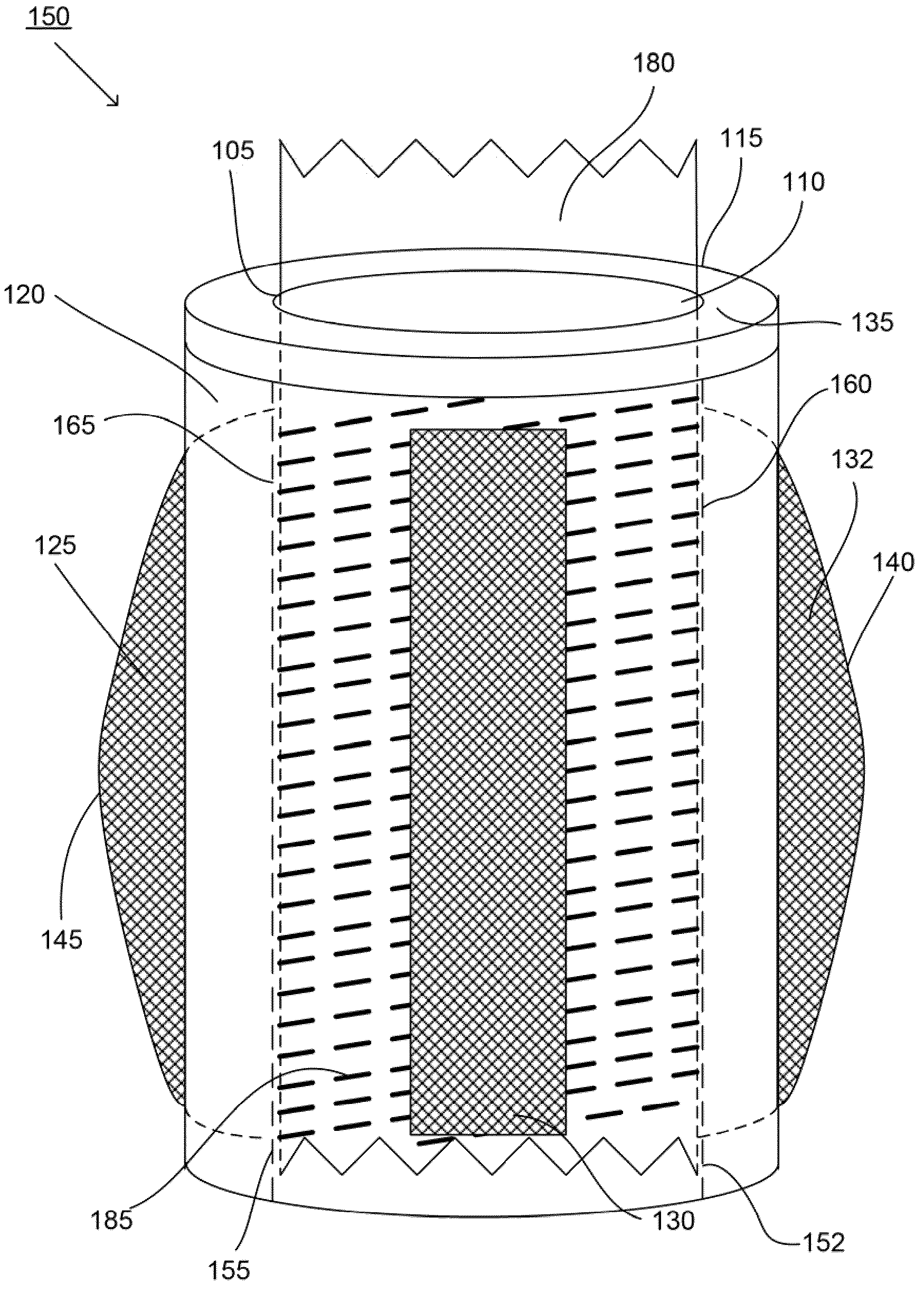
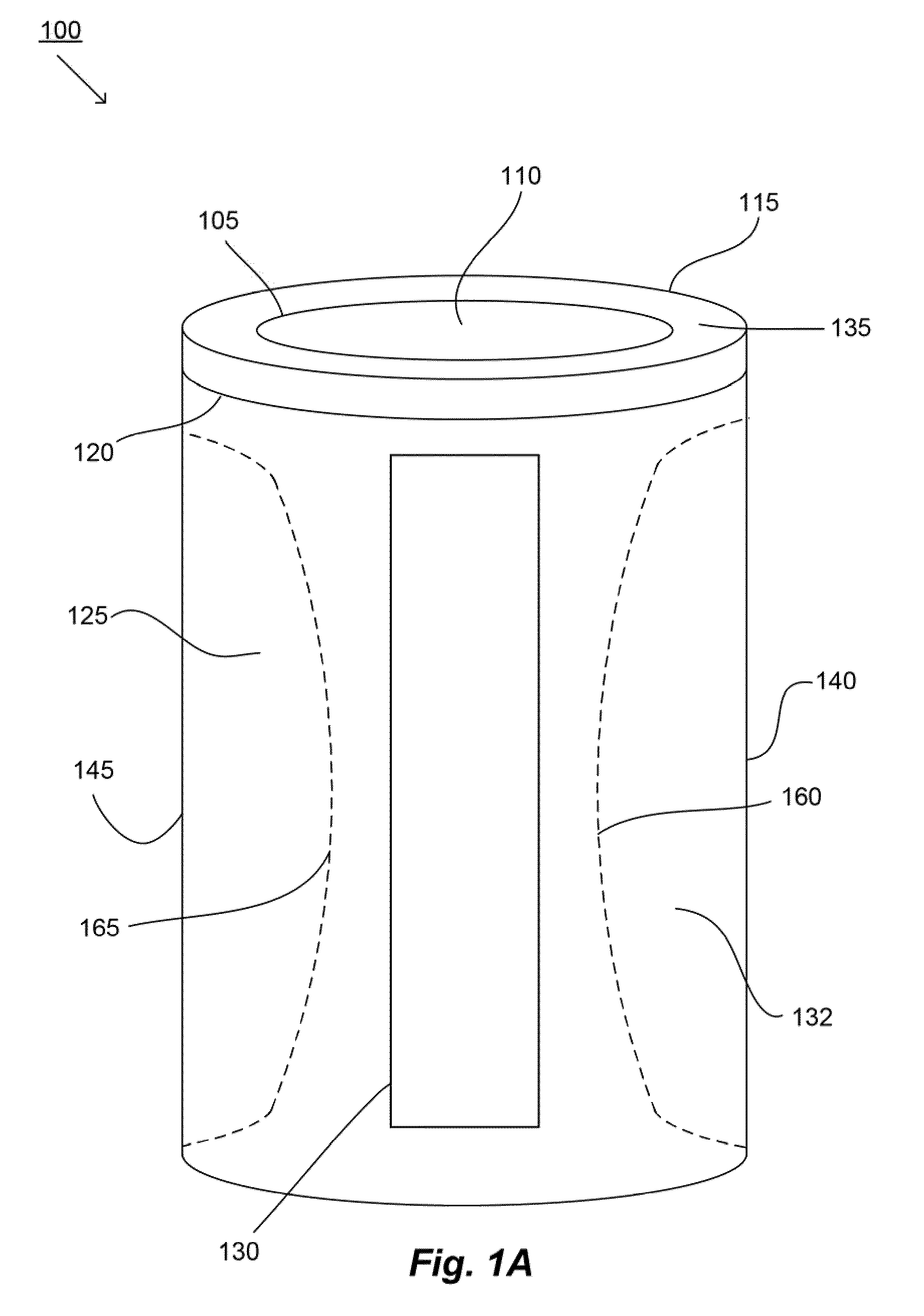
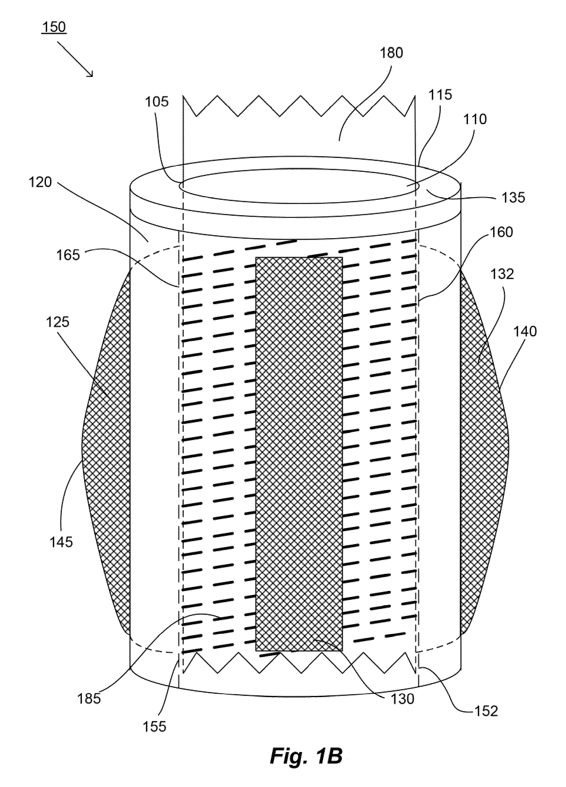
[0064]The present invention is directed generally to bio-medical device(s) and method(s). More specifically, the embodiments may include a device(s) and method(s) used in various medical treatments. For example, various embodiments may include device(s) and method(s) that relate to reconstructing, replacing, attaching, connecting or repairing structural tissue such as bones, ligaments, etc. in living cells or organisms. In various embodiments, the present invention may include one or more anchor(s) mechanisms used to attach or repair structural tissue, for example, bones, etc. The various anchor mechanisms may be of a unique design that increases the purchase of, for example, a screw or a bolt. The various anchor mechanisms may be of a type that includes one or more expandable members. The expandable members may be of various geometries and wall designs for use in various types of structural tissue and opening in the structural tissue. In various embodiments, the anchoring mechanism...


PUM


Abstract

The present invention is directed generally to a bio-medical system(s) and method(s). More specifically, some embodiments may include system(s) and method(s) used in medical treatment(s). Various embodiments may include medical system(s) and method(s) that may use an anchoring mechanism and screw (bolt, etc.) arrangement that increases the strength of attachment. Some embodiments may further include, for example, an anchoring mechanism that expands upon insertion of a screw (bolt, etc.) into an opening. Some embodiments may include, for example, a system(s) and method(s) for improvement of structural tissue (e.g., bone, cartilage) fixation and safety. Further, some embodiments may also include, for example, an anchoring mechanism and screw (bolt, etc.) system that may be utilized in orthopedic procedures. Still some embodiments may further include system(s) and method(s) providing improved screw fixation and enhanced stabilization in structural tissue or fracture repair. Various embodiments may include multiple anchor mechanisms and anchor mechanism holding means.

Description

[0001]This application is a continuation of U.S. patent application Ser. No. 12 / 124,416 and claims the benefit thereof and of U.S. patent application Ser. No. 12 / 124,446 both filed on May 21, 2008, both of which applications claim the benefit of continuation-in-part of U.S. patent application Ser. No. 11 / 550,402, filed on Oct. 17, 2006; this application also claims the benefit of U.S. patent application Ser. No. 11 / 550,402, filed on Oct. 17, 2006 and U.S. Provisional Application No. 60 / 596,734, filed Oct. 17, 2005, the entire disclosures of which are all hereby incorporated by reference, in their entirety, as if set forth fully herein.BACKGROUND[0002]1. Field of the Invention[0003]The present invention relates to the field of bio-medical devices and methods, more specifically, a, device(s) and method(s) used in medical treatment(s).[0004]2. Description of Related Art[0005]There are several systems and methods previously described which are utilized in medical treatments relating to ...

Claims


Application Information

Patent Timeline
Patent Type & Authority Applications(United States)
IPC IPC(8): A61B17/86
CPCA61B17/686A61B17/70A61B17/8872A61B2017/8655
Inventor GOOCH, HUBERT L.
Owner GOOCH HUBERT L
Why Eureka
Try Eureka