Overlay network traffic detection, monitoring, and control

a technology of overlay network and traffic detection, applied in the direction of data switching network, instruments, digital transmission, etc., can solve the problems of preventing other users from communicating, affecting the detection of overlay network traffic, and difficult to discover the existence of overlay network

Inactive Publication Date: 2010-07-22
OKI ELECTRIC IND CO LTD
View PDF8 Cites 33 Cited by
  • Summary
  • Abstract
  • Description
  • Claims
  • Application Information

AI Technical Summary

Benefits of technology

[0029]Artifacts such as packet delays, dropped packets, or bit errors may be added to the network traffic and the resulting effects on the traffic profiles may be observed to identify overlay network traffic paths.

Problems solved by technology

Peer-to-peer networks and other types of overlay networks may use up a large amount of the underlying network's bandwidth, thereby blocking other users' communication, or may conduct illegal activities such as transmitting illegal information or offering illegal services.
The type of information that needs to be obtained about an overlay network includes, for example, the presence of encrypted or tunneled traffic, the communication paths of the traffic, the volume of the traffic, and the communication protocols used, but such information can be difficult to obtain.
In fact, it can be difficult to discover even the existence of overlay networks.
One reason for these difficulties is that the length and content of packets may be modified at the nodes of an overlay network, as illustrated in FIG. 1, making it difficult for an Internet service provider (ISP) to assess the packet flow.
Because of the flow separation and integration performed at the nodes PC50, PC60 of the overlay network, by analyzing just the packet traffic it is difficult for the ISP to learn of the existence of the overlay network and determine what type of traffic it is carrying.
One problem with the methods disclosed in JP 2004-343186 is that the information obtained by the traffic separator is limited to information held by nodes that have made contact with the decoy terminal and information about the flow of traffic transmitted and received by such nodes; the traffic separator cannot obtain information about other nodes in the peer-to-peer network.
Another problem is that no method of specifically blocking peer-to-peer network traffic without blocking other traffic handled by the peer-to-peer network nodes is provided.
Accordingly, this method fails to identify peer-to-peer traffic if the personal computers belonging to the peer-to-peer network are unknown, or if authentication is necessary to join the peer-to-peer network.
A problem in this method is the reliability of the statistical model.
This method is inapplicable when it is difficult to detect peer-to-peer messages, or when their content is encrypted and cannot be decrypted.
This method is inapplicable when specific content cannot be recognized.
A precondition for this method is that the network operator can detect and control flow paths, however, so this method is inapplicable when users implement an overlay network on their own.

Method used


Image

  • Overlay network traffic detection, monitoring, and control
  • Overlay network traffic detection, monitoring, and control
  • Overlay network traffic detection, monitoring, and control

Examples


first embodiment

[0044]The equipment in the first embodiment includes a plurality of overlay traffic information collectors 100-1, 100-2, 100-3, 100-4, . . . as shown in FIG. 3. A general one of these overlay traffic information collectors 100-1, 100-2, 100-3, 100-4, . . . will be referred to as an overlay traffic information collector 100. Each of these overlay traffic information collectors 100 may be mounted in or on a router, for example, or in a personal computer belonging to a cooperating subscriber, to receive traffic in transit on a network.

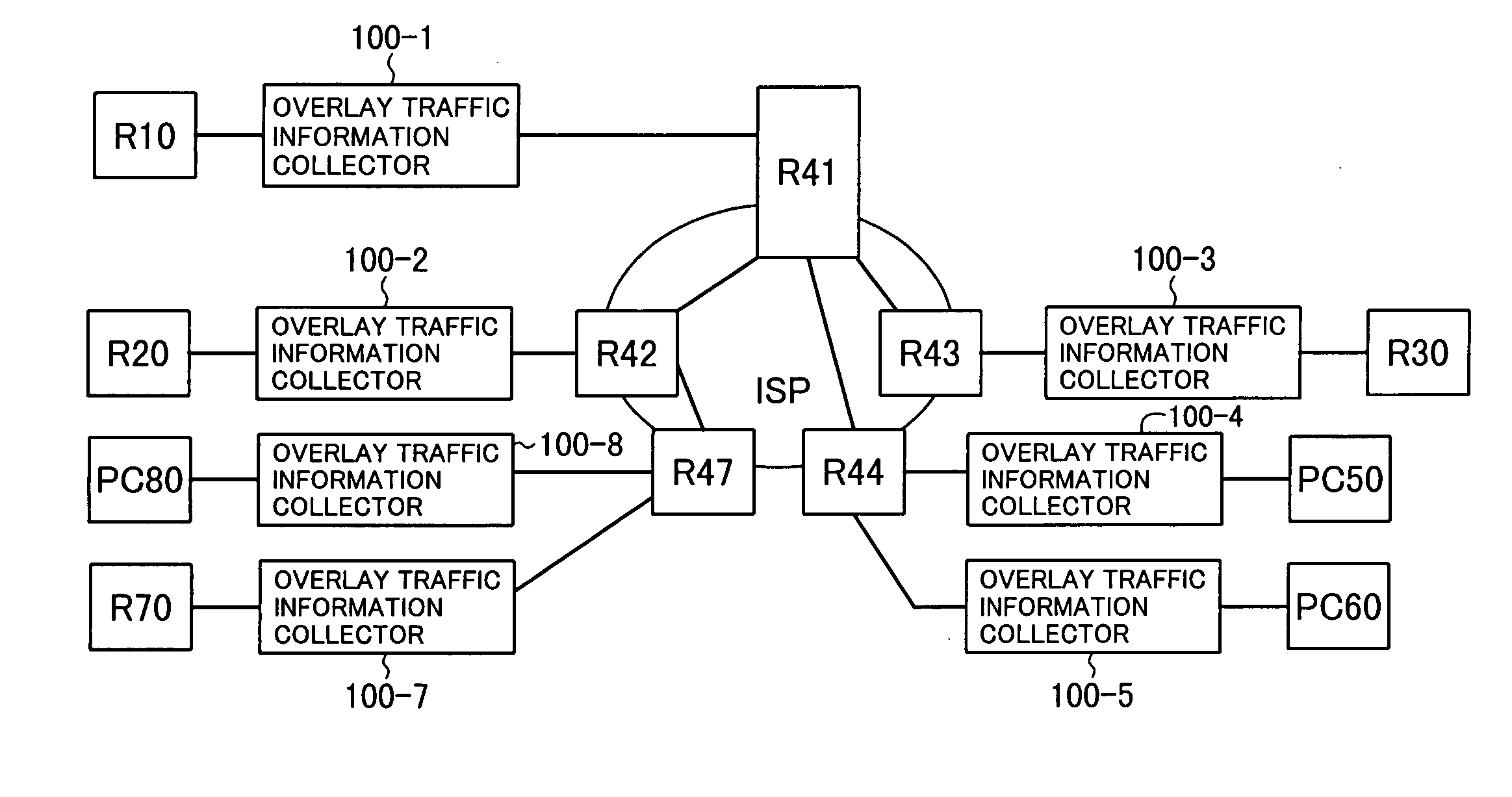
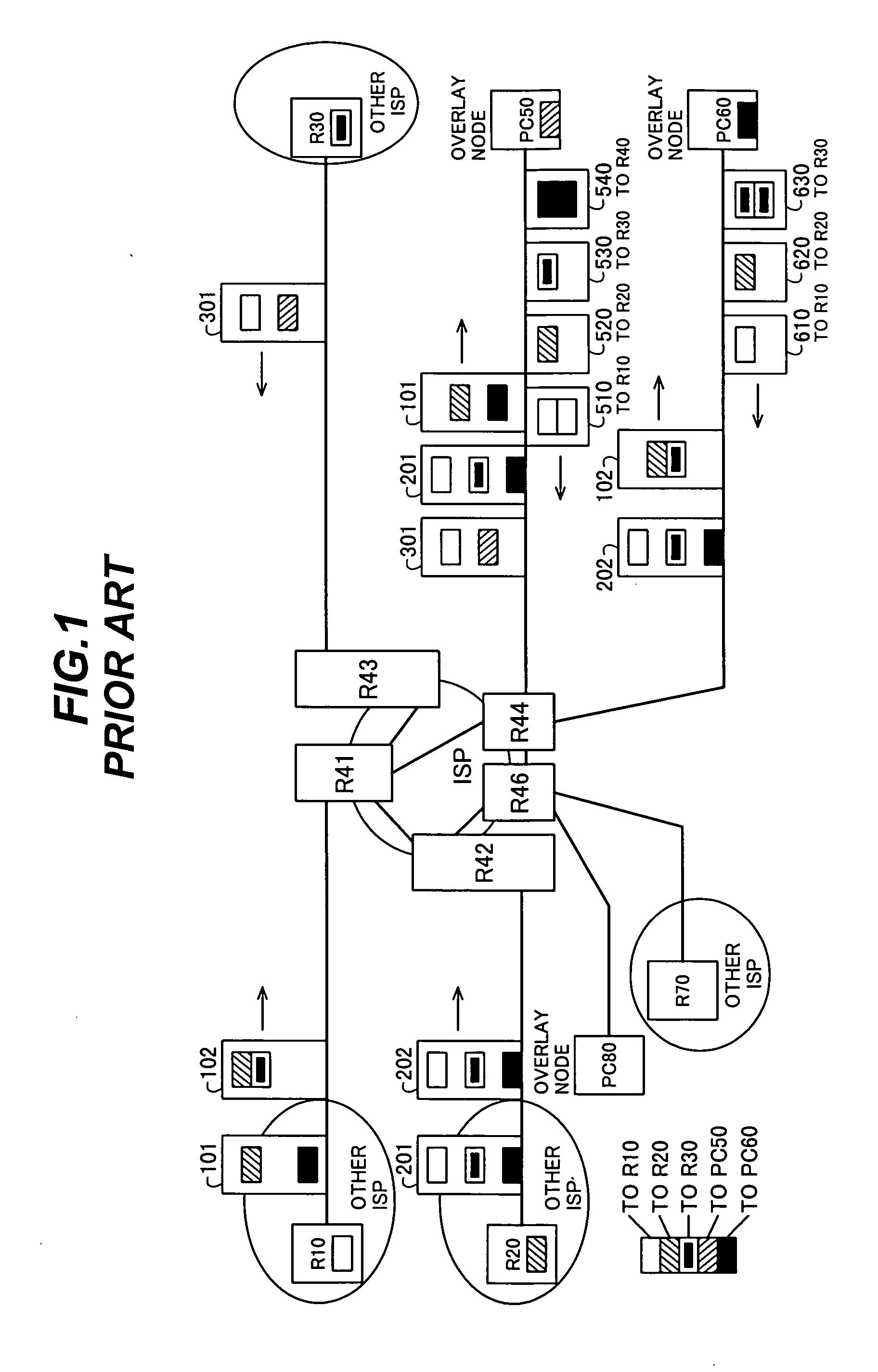
[0045]FIG. 4 shows overlay traffic information collectors 100-1, . . . , 100-5, 100-7, 100-8 installed in the network that was shown in FIG. 1. Each overlay traffic information collector is preferably located between two routers belonging to different ISP networks or between a router belonging to an ISP network and a subscriber's personal computer. Overlay traffic information collector 100-1, positioned between routers R41 and R10, is an example of the fo...

second embodiment

[0120]The overlay traffic detection, monitoring, and control system in the second embodiment of the invention will now be described.

[0121]Referring to FIG. 8, in addition to the overlay traffic information collectors used in the first embodiment, the second embodiment employs a node including a probe information transmitter-receiver 200. The probe information transmitter-receiver 200 has an overlay function enabler 210, a control unit 213, and a communication unit 214.

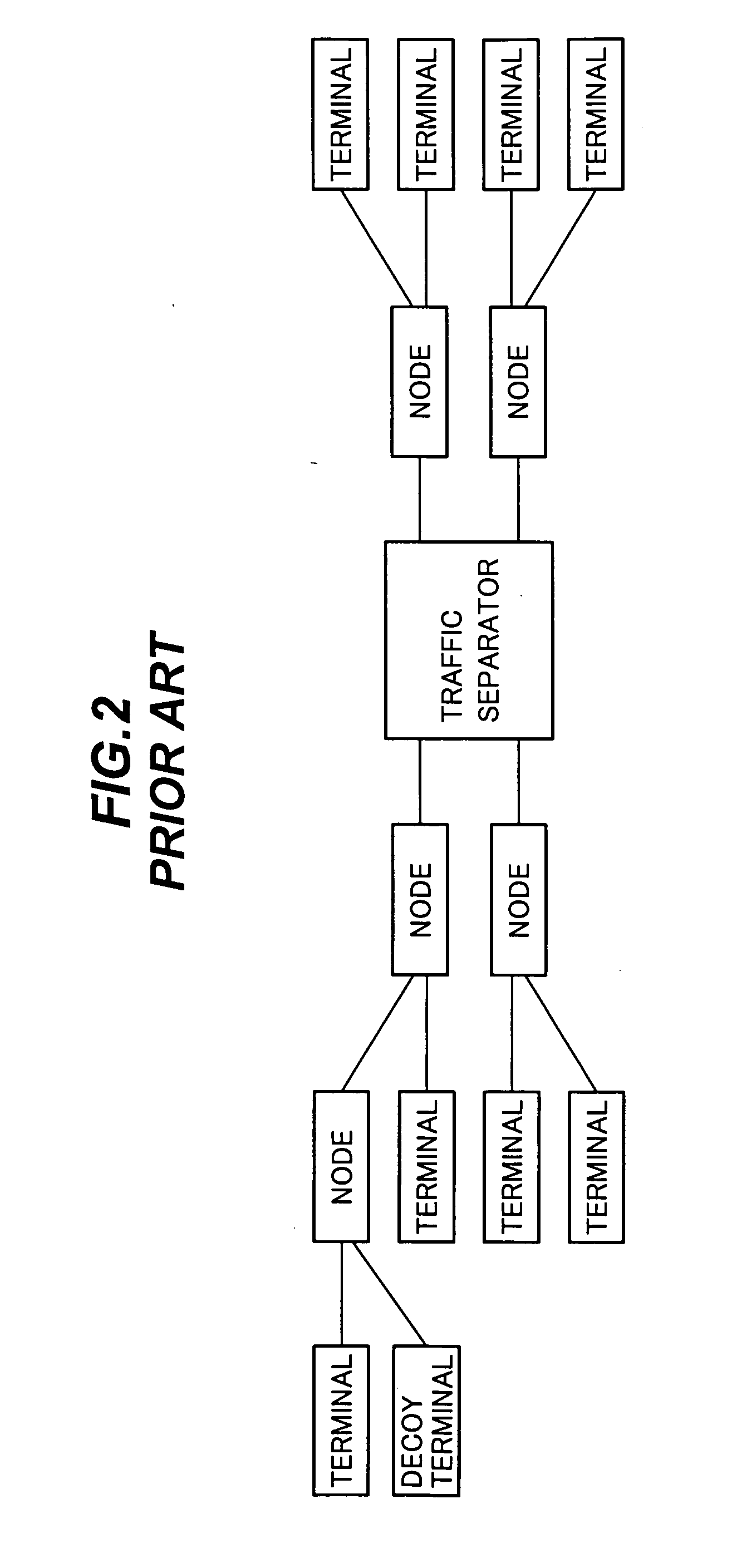
[0122]The system in the second embodiment functions particularly effectively on file-sharing overlay networks. The node including the probe information transmitter-receiver 200 functions as a decoy in such networks, but differing from the prior art, the probe information transmitter-receiver 200 can produce information about overlay network nodes to which the decoy terminal is not directly connected, even about nodes with which the personal computer on which the probe information transmitter-receiver 200 is installed h...

third embodiment

[0136]The overlay traffic detection system and monitoring and control system in the third embodiment will now be described.

[0137]Referring to FIG. 10, the third embodiment replaces the overlay traffic information collectors used in the first and second embodiments with enhanced overlay traffic information collectors 300. FIG. 10 shows two enhanced overlay traffic information collectors 300-1, 300-2. Overlay traffic information collector 300-1 includes a mirroring device 311, packet passer 312, traffic measurement unit 313, traffic profiler 314, communication unit 315, and correlator-evaluator-thresholder 316, which are generally similar to the corresponding elements in the overlay traffic information collector 100-1 in FIG. 3, and also includes a keyword measurement unit 317 and a similarity evaluator 318. Overlay traffic information collector 300-2 has a generally similar internal structure (not shown), including the keyword measurement unit and possibly the similarity evaluator.

[0...


PUM


Abstract

An overlay network traffic detection system deploys traffic measurement units at multiple points on a network, creates profiles of the network traffic measured at each point, and then compiles the traffic profiles obtained at different points. The compiled profile of outbound traffic originating at a node is compared with the compiled profile of inbound traffic addressed to the same node. A strong correlation between the two profiles indicates that the node is relaying overlay network traffic. Further information can be gained by profile screening, by active interference in the traffic flow, by launching known information into the network at known times and observing its effect on the traffic profiles, and by observing keyword distributions in non-encrypted traffic.

Description

BACKGROUND OF THE INVENTION[0001]1. Field of the Invention[0002]The present invention relates to the detection, monitoring, and control of overlay network traffic, including peer-to-peer network traffic.[0003]2. Description of the Related Art[0004]Much of the traffic that flows on, for example, the Internet is encrypted. Much traffic also flows through peer-to-peer (P2P) networks and overlay networks, in which transmission paths that operate as virtual tunnels are established between user nodes that operate as relay points.[0005]The term ‘overlay network’ means a network structured on an underlying network and using the underlying network's data transmission function, but having a routing function differing from that of the underlying network. The term ‘peer-to-peer network’ refers to a network of computers that interact on a peer basis. In a peer-to-peer network of personal computers (PCs), for example, each personal computer performs the same network functions, operating sometimes...

Claims


Application Information

Patent Timeline
Patent Type & Authority Applications(United States)
IPC IPC(8): G06F15/173H04L12/70
CPCH04L41/142H04L43/12H04L43/16H04L45/64H04L45/70H04L43/026
Inventor NAKAHIRA, YOSHIHIRO
Owner OKI ELECTRIC IND CO LTD
Why Eureka
Try Eureka