Method for opc correction

a technology of optical proximity and correction method, applied in the field of optical proximity correction (opc) method, can solve the problems of not taking into account the lithography process window, mask layout still has deficiencies, etc., and achieve the effect of simulation of image quality step

Active Publication Date: 2010-07-22
VANGUARD INTERNATIONAL SEMICONDUCTOR CORPORATION
View PDF7 Cites 14 Cited by
  • Summary
  • Abstract
  • Description
  • Claims
  • Application Information

AI Technical Summary

Benefits of technology

[0007]Due to the issues described, the invention provides an optical proximity correction method, comprising establishing an optical proximity correction (OPC) model, performing an OPC correction step to correct segments of a layout pattern. The OPC correction steps comprise defining an edge of the layout pattern neighboring a hot-spot location on a mask to locate a target point and a dissection point. The step of locating the target point and the dissection point includes setting a plurality of pre-target points and pre-dissection points, and electing a target point and a dissection point for correcting the segments of the layout pattern from the pre-target points and pre-dissection points according to image quality of the pre-target points and pre-dissection points.
[0008]In another aspect, the invention provides an optical proximity correction method, comprising establishing an optical proximity correction (OPC) model and performing a correcting layout and simulating image quality step. The OPC method comprises setting a plurality of pre-target points and pre-dissection points, electing a target point and a dissection point for correcting the segments of the layout pattern from the pre-target points and pre-dissection points according to a normalized image log slope (NILS) and a mask error enhancement factor (MEEF) of the pre-target points and pre-dissection points, and outputting a layout according to the corrected pattern.

Problems solved by technology

Although the conventional art allows exposure of patterns with good conformity, the lithography process window, however, is not taken into account.
Therefore, the resulting mask layout still has deficiencies.

Method used


Image

  • Method for opc correction
  • Method for opc correction
  • Method for opc correction

Examples


Embodiment Construction

[0014]The following description is of the contemplated mode of carrying out the invention. This description is made for the purpose of illustrating the general principles of the invention and should not be taken in a limiting sense, not for limiting the invention.

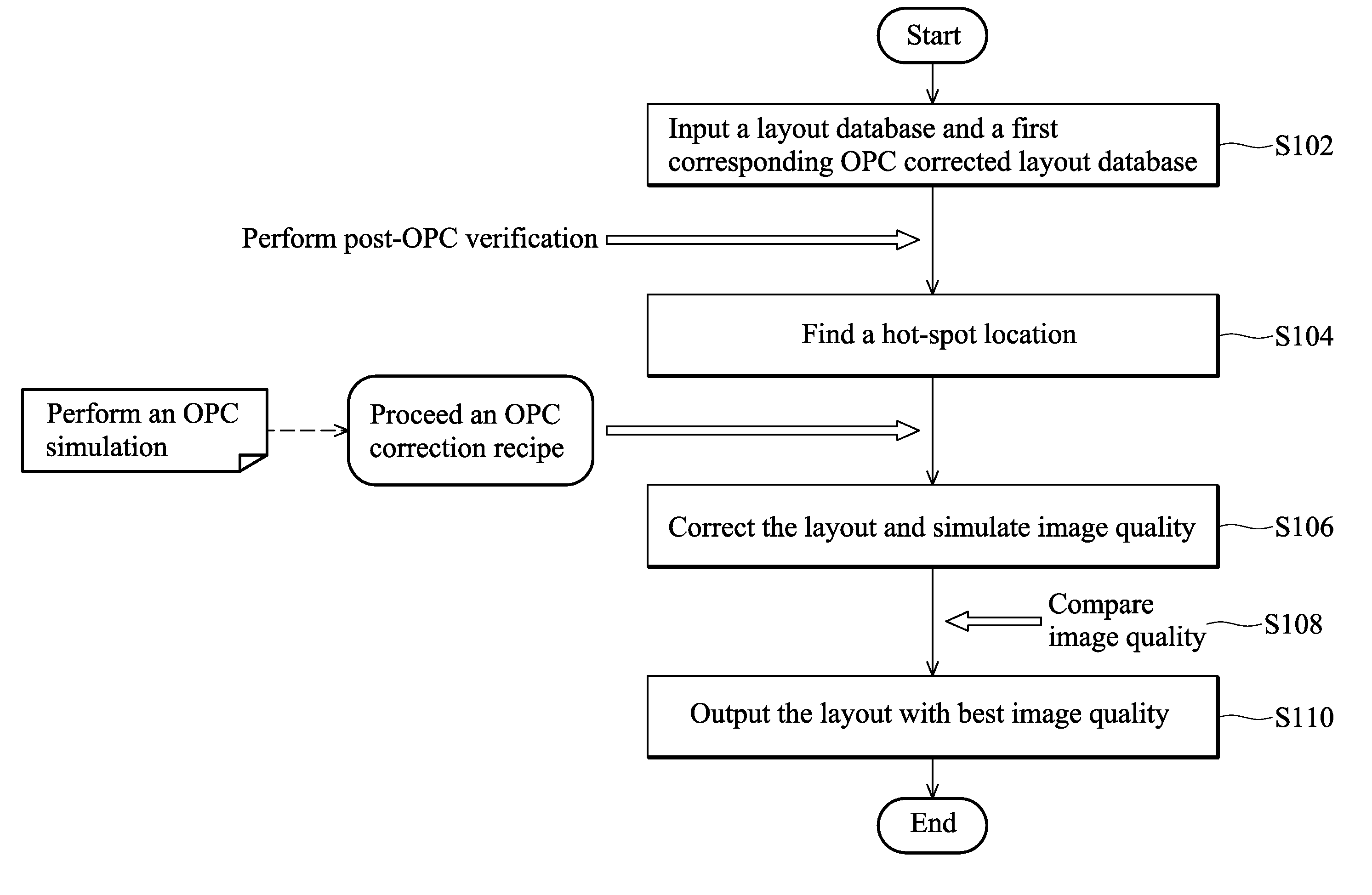
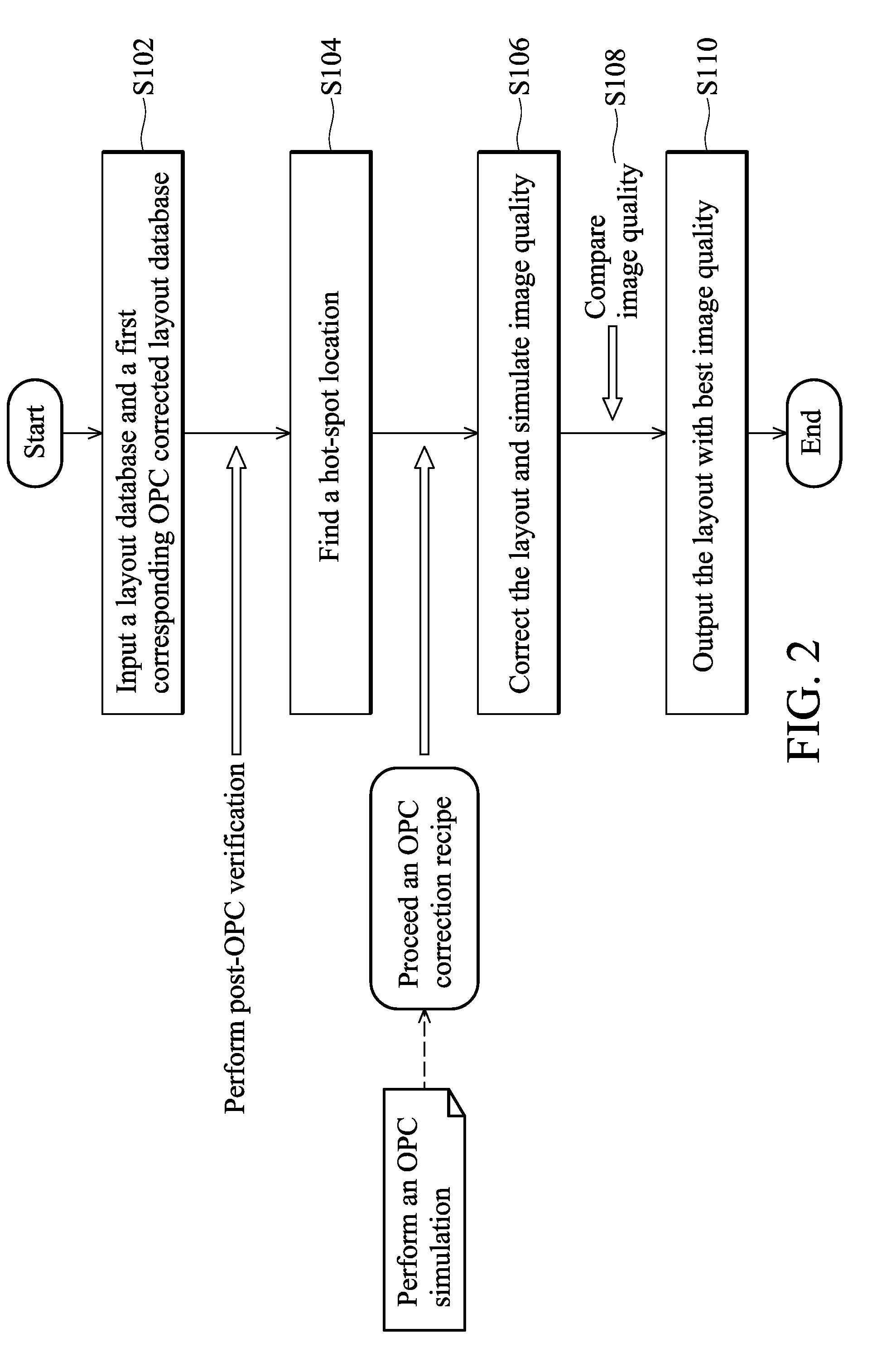
[0015]Referring to FIG. 2 and FIG. 3, in which FIG. 2 shows a flow chart of an embodiment of the invention and FIG. 3 supplements illustration of the embodiment. To begin, a layout database and a first corresponding OPC corrected layout database are inputted in step S102. Next, post-OPC verification is performed to verify the layout and hot-spot locations are located in step S104, wherein the hot-spot locations are critical layout regions of the lithography process and are of the troublesome areas of the lithography process window. Thereafter, an OPC simulation is performed and an OPC correction recipe is proceeded to correct the layout and simulate image quality at the hot-spot locations in step S106. Next, a comparison of...


PUM


Abstract

An optical proximity correction method is disclosed, comprising establishing an optical proximity correction (OPC) model, and performing an OPC correction step to correct segments of a layout pattern. The OPC correction comprises the step of defining an edge of the layout pattern neighboring a hot-spot location on a mask to locate a target point and a dissection point. The step of locating the target point and the dissection point includes setting a plurality of pre-target points and pre-dissection points, and electing a target point and a dissection point for correcting the segments of the layout pattern from the pre-target points and pre-dissection points according to image quality of the pre-target points and pre-dissection points.

Description

BACKGROUND OF THE INVENTION[0001]1. Field of the Invention[0002]The invention relates to an optical proximity correction (OPC) method, and more particularly relates to an OPC correction recipe of an optical proximity correction method.[0003]2. Description of the Related Art[0004]OPC methods are used to eliminate critical dimension variation of lithography masks during fabrication. The transfer of original patterns to a semiconductor substrate is corrected using a software program involving computations, in which different patterns from the original patterns are obtained. The patterns corrected by OPC are then transferred to a mask. After the OPC correction, the pattern formed by light passing through the mask and irradiating the semiconductor substrate is similar to the original pattern.[0005]FIGS. 1A and 1B show correction steps of a conventional optical proximity correction method. Referring to FIG. 1A, after an OPC model is established, the step of correcting the layout pattern a...

Claims


Application Information

Patent Timeline
Patent Type & Authority Applications(United States)
IPC IPC(8): G06F17/50
CPCG03F1/36
Inventor WANG, LI-MING
Owner VANGUARD INTERNATIONAL SEMICONDUCTOR CORPORATION
Why Eureka
Try Eureka