Efficient and light weight thermoelectric waste heat recovery system

a thermoelectric waste heat recovery and efficient technology, applied in the direction of machine operation, light and heating apparatus, transportation and packaging, etc., can solve the problem that approximately 30% of the energy contained in automotive fuel may be lost to the environment, and achieve high electrical output, high thermal conductivity, and improved utilization of hot fluids

Inactive Publication Date: 2010-07-29
UT BATTELLE LLC +1
View PDF15 Cites 38 Cited by
  • Summary
  • Abstract
  • Description
  • Claims
  • Application Information

AI Technical Summary

Benefits of technology

[0007]This invention provides a combination of (i) a light weight, open pore, foam material with very high thermal conductivity and (ii) a thermoelectric device for improved utilization of a hot fluid stream associated with a vehicle engine (and / or a relatively cool stream of ambient air). This combination is devised to produce a high electrical output for powering an electrical device on a vehicle.
[0008]In one embodiment the high thermal conductivity foam may be carbon foam, a material formed from graphite fibers. Such a carbon material may be produced from pitch. The graphitic foam body or layer is used to increase heat transfer from a hot engine exhaust stream or a hot engine coolant stream to the high temperature side of a thermoelectric device. The foam body is designed and used to increase the temperature of the high temperature side. In another embodiment, a graphitic foam body may be used to improve heat transfer between ambient air and the low temperature side of a thermoelectric device. Again, the foam body is designed and used to decrease the temperature of the low temperature side of the thermoelectric.
[0009]Thus, the foam is used to increase the temperature difference between the hot and cold sides of the thermoelectric device so as to increase the effectiveness of the device. The high open pores of the foam permit, for example, at least some exhaust gas flow through it for improved heat transfer to the hot side of the thermoelectric device. And, likewise, the foam may permit internal ambient air flow for improved heat transfer from the thermoelectric and a lower temperature at its cold side.
[0010]The low density of the foam allows the design of effective heat transfer paths to and from the thermoelectric device(s) without adding significant weight to a vehicle.

Problems solved by technology

For example, approximately 30% of the energy contained in automotive fuel may be lost to the environment as thermal energy in the exhaust gas of an internal combustion engine.

Method used


Image

  • Efficient and light weight thermoelectric waste heat recovery system
  • Efficient and light weight thermoelectric waste heat recovery system
  • Efficient and light weight thermoelectric waste heat recovery system

Examples


Embodiment Construction

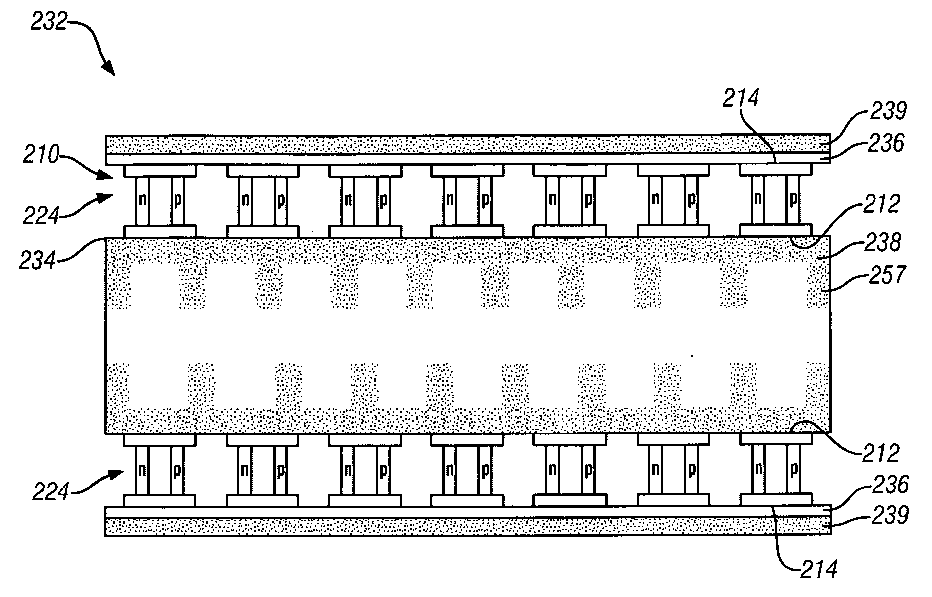
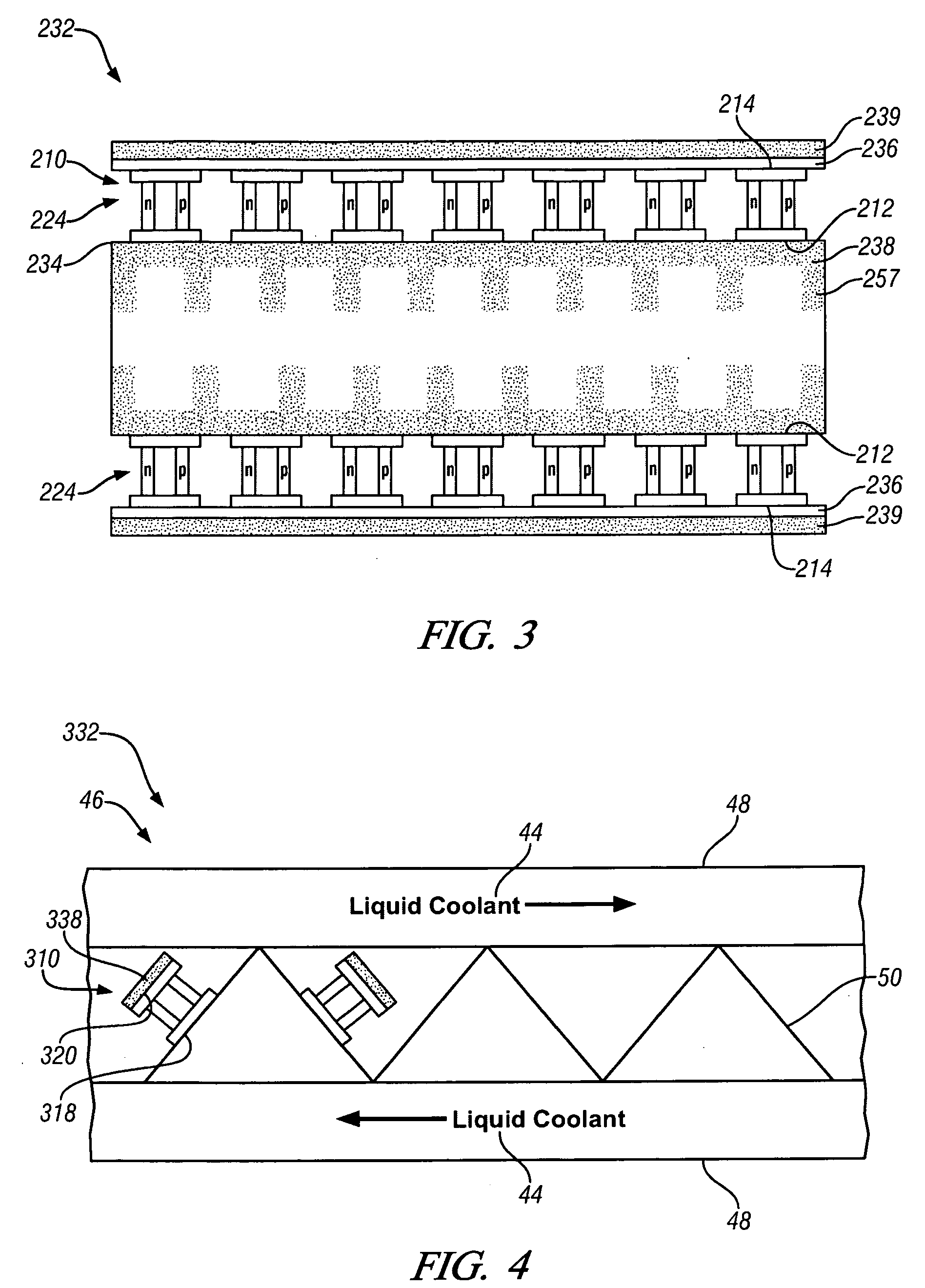
[0016]One embodiment includes a thermoelectric system including high conductivity foam to convert waste thermal energy captured from a combustion engine into electrical power. The waste thermal energy may be captured from exhaust gases or coolant from the internal combustion engine. The waste thermal energy may include any thermal energy which is available after the internal combustion engine of a vehicle has performed its normal functions, such as, for example, heat remaining in the exhaust gases or heat transferred to a liquid coolant.

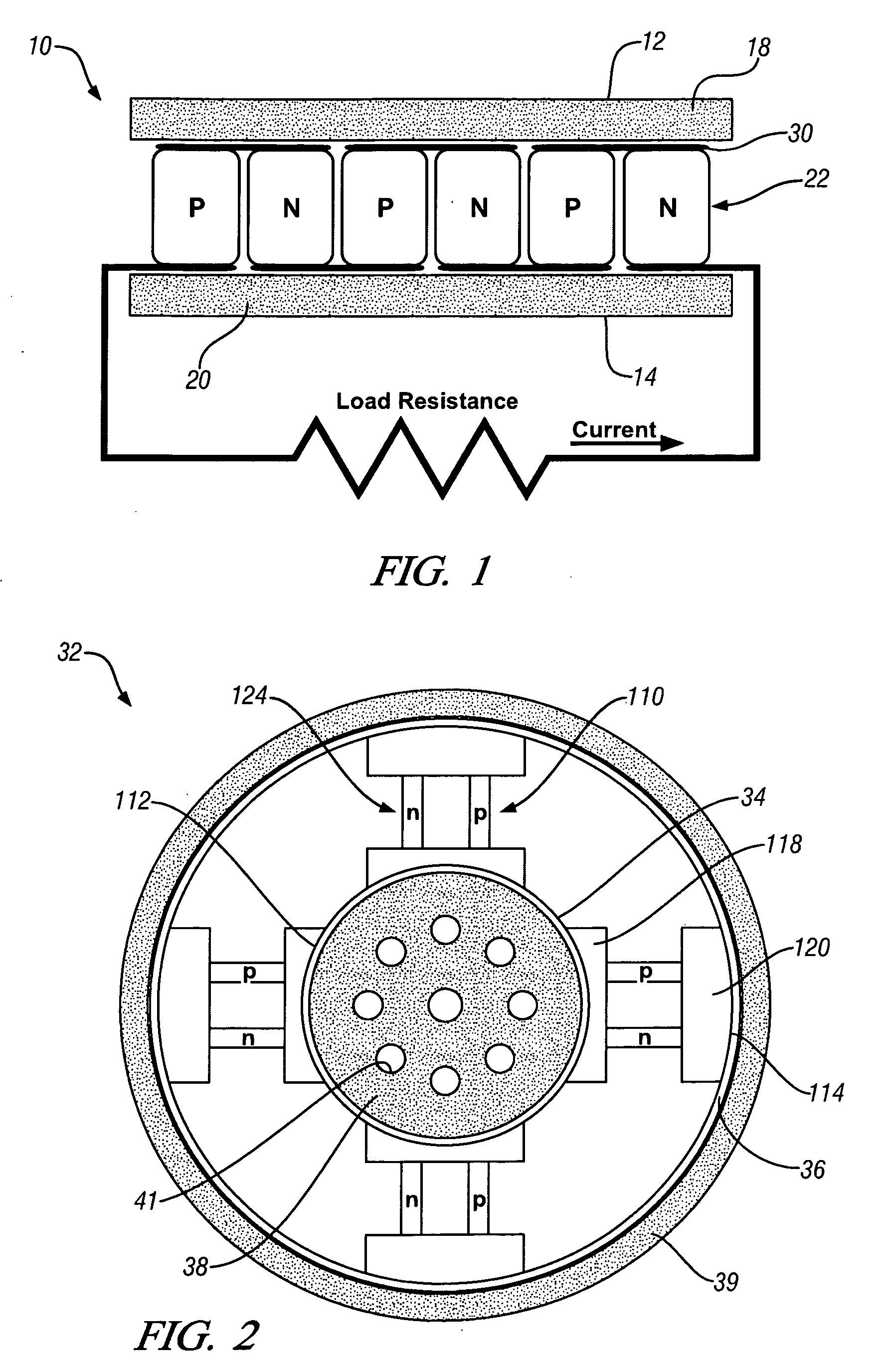
[0017]FIG. 1 shows a thermoelectric device or module 10 for producing an electrical potential and a direct electrical current. A thermoelectric device is a solid-state device with no moving parts which is capable of using a temperature differential to generate electrical power without mechanical motion. The thermoelectric device 10 includes a high temperature or hot side 12 and a low temperature or cold side 14. The high temperature side 12 is in con...


PUM


Abstract

One embodiment includes an on-board thermoelectric vehicle system for generating electrical energy using a heated fluid stream, including at least one thermoelectric device having a high temperature junction and a low temperature junction, and a body of high conductivity foam shaped and located to increase heat transfer from the heated fluid stream to the high temperature junction or to increase heat transfer from the low temperature junction of the thermoelectric device.

Description

[0001]The United States Government has rights in this invention pursuant to Cooperative Agreement No. DE-FC26-04NT42278 awarded by the United States Department of Energy. The United States Government has rights in this invention pursuant to contract no. DE-AC05-00OR22725 between the United States Department of Energy and UT-Battelle, LLC.TECHNICAL FIELD[0002]This invention pertains to the use of thermoelectric devices in combination with hot fluid streams produced by an operating internal combustion engine. The high temperature sides of the devices are in heat transfer contact with, for example, the hot engine exhaust stream and the low temperature sides are in heat transfer contact with ambient air so as to produce electrical power. More specifically this invention pertains to the use of light weight, high thermal conductivity foam materials in contact with the high temperature sides and / or low temperature sides of the devices to increase their output of electrical power.BACKGROUND...

Claims


Application Information

Patent Timeline
Patent Type & Authority Applications(United States)
IPC IPC(8): F25B21/02B60H1/32
CPCH01L35/30H10N10/13
Inventor YANG, JIHUIWANG, HSINKLETT, JAMES WILLIAMS
Owner UT BATTELLE LLC
Why Eureka
Try Eureka