Gyrometer in surface technology, with out-of-plane detection by strain gauge

a strain gauge and surface technology, applied in the field of microsensors, can solve the problem that the device is not able to detect rotation around an axis situated in its own plan

Active Publication Date: 2010-07-29
COMMISSARIAT A LENERGIE ATOMIQUE ET AUX ENERGIES ALTERNATIVES
View PDF11 Cites 29 Cited by
  • Summary
  • Abstract
  • Description
  • Claims
  • Application Information

AI Technical Summary

Benefits of technology

[0027]Such a device makes it possible to detect a rotation imposed around the first axis, situated in the plane of the device itself. The detection done is that of a movement outside this plane, around the second axis of rotation.

Problems solved by technology

Such a device is not able to detect rotatio

Method used


Image

  • Gyrometer in surface technology, with out-of-plane detection by strain gauge
  • Gyrometer in surface technology, with out-of-plane detection by strain gauge
  • Gyrometer in surface technology, with out-of-plane detection by strain gauge

Examples


first embodiment

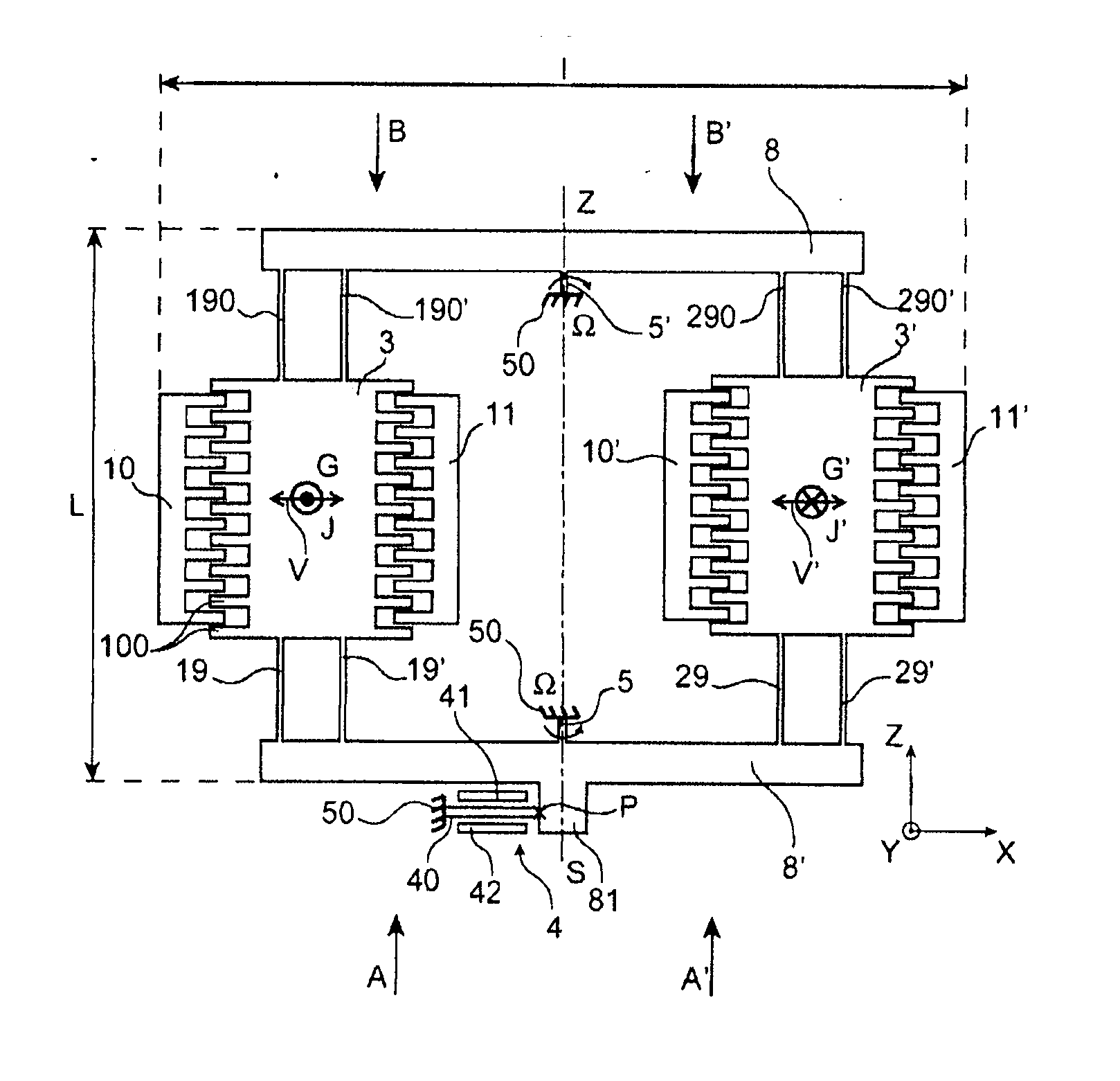
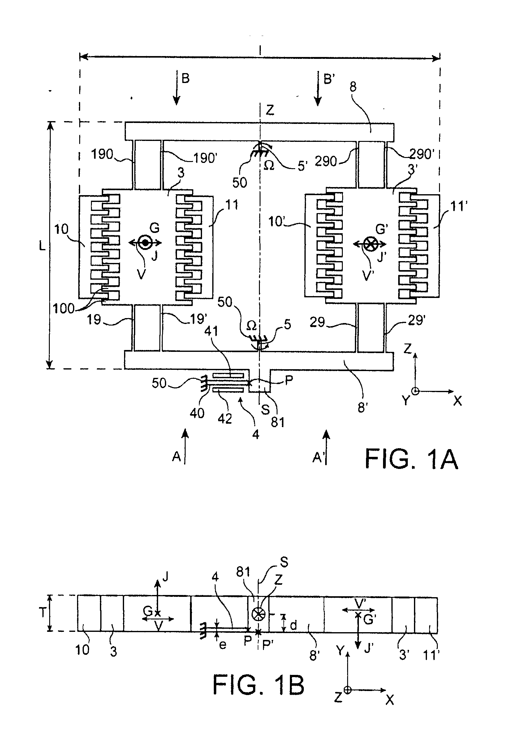
[0055]the invention concerns a gyrometer-type device illustrated in FIG. 1A (top view) and 1B-1F (cross-sectional views).

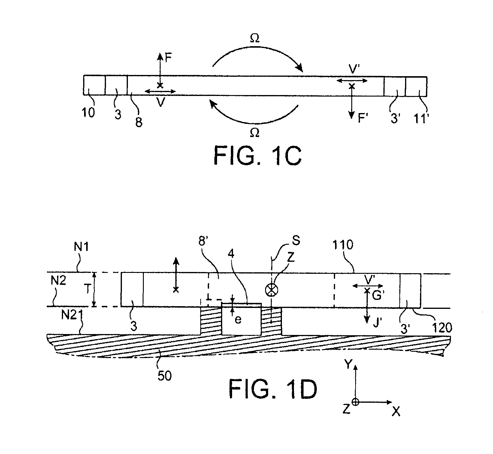
[0056]It involves a gyrometer-type sensor resonating with gauges positioned so as to measure a rotation. This sensor is planar (plane XZ) and undergoes planar excitation in its plane. If the device is subjected to rotation around an axis Z, arranged in its plane, Coriolis forces drive it in rotation around this axis, but the movement J corresponding to this rotation is situated outside the plane of the sensor.

[0057]FIG. 1A shows that this sensor comprises an assembly of two masses 3, 3′ and an assembly of connecting arms 8, 8′, 19, 19′, 29, 29′, 190, 190′, 290, 290′. Idle, the arms and the masses are all situated in the plane of the device. Arms 8, 8′ are connected to zones 5, 5′ forming a pivot around an axis Z on which they are aligned. This axis is situated in the plane of two masses 3, 3′. It is the axis around which the movement J corresponding to a rotation ...

second embodiment

[0109]the invention will be described in connection with FIGS. 2A and 2B. It again concerns a sensor of the gyrometer type, of the same type as that of the previous embodiment, the differences being primarily related to the strain gauges.

[0110]In this embodiment, there are four strain gauges arranged differentially, two for each pivot zone or for each extension 81, 82 of each zone forming a pivot. The extension 82 and the pivot 5′ have the same relative arrangement, in relation to the arm 8, as the pivot 5 and the extension 81 in relation to the arm 8′. In the example illustrated in FIG. 2A, the two gauges 6, 6′ are directly applied to the extension zone 82 of the pivot 5′ for the upper primary arm 8. Each of these two gauges is also fixed to the substrate 50. A movement of the arm 8 therefore imposes a force on each of the gauges 6, 6′ in the plane of the sensor. These two gauges are arranged symmetrically to each other in relation to the plane S and in relation to the axis Z. Two ...

third embodiment

[0131]a device according to the invention is illustrated in front view in FIG. 3A.

[0132]This device, like the device described in the preceding embodiments of the invention, is made up of three zones. It has essentially the same dimensions as those indicated above, in thickness T, as well as in dimensions L and 1 in the plane XZ.

[0133]A first zone includes two masses 3 and 3′, symmetrical to each other in relation to a plane S perpendicular to the plane of the substrate. The intersection between this plane and the plane of the substrate forms an axis of direction Z. The axis X and the axis Y are defined as in the first embodiment. The thickness T of this first zone is between some 100 nm and some 10 μm, for example 1 μm.

[0134]The first zone contains the two masses as well as the primary connecting arms 80, 80′ and 81, 81′ oriented along the axis X and secondary arms 19, 19′, 190, 190′, 29, 29′, 290, 290′ oriented along the axis Z.

[0135]Each of the primary arms 80, 80′, 81, 81′ is el...


PUM


Abstract

The invention concerns a gyrometer-type device, comprised in a substrate (2, 50), and characterized in that it includes:
    • at least one mass (3, 3′, 31, 32, 33) defining, idle, a plane, arranged at a distance from an axis (Z, H, H′) of rotation contained in this plane, this mass being able to be caused to vibrate in this plane, perpendicular to the axis of rotation (Z),
    • at least two connecting arms to connect said mass to said axis of rotation;
    • means forming, for at least one of the arms, at least one connection with the substrate for a rotation around said axis of rotation,
    • at least one strain gauge, for detecting the rotational movement.

Description

TECHNICAL FIELD AND BACKGROUND OF THE INVENTION[0001]The invention concerns the field of micro-sensors, in particular in silicon, for example inertial sensor units, in particular gyrometers.[0002]It is applicable in various fields, including the automobile, mobile telephony and avionics fields.[0003]In a known manner, resonant sensors can be realized in volume technology, in which case the sensitive element of the sensor is made in the entire thicknesses of a silicon or quartz substrate, by using wet etching; such a technique is described in document FR 2 763 694.[0004]Document EP-1 626 282 describes a gyrometer capable of detecting movement along a plane perpendicular to the plane of the device.[0005]Such a device is not able to detect rotation around an axis situated in its own plane.[0006]The invention therefore aims to propose a new type of gyrometer-type device, making it possible to perform a detection around an axis situated in its own plane.BRIEF DESCRIPTION OF THE INVENTION...

Claims


Application Information

Patent Timeline
IPC IPC(8): G01C19/56
CPCG01C19/574
Inventor ROBERT, PHILIPPE
Owner COMMISSARIAT A LENERGIE ATOMIQUE ET AUX ENERGIES ALTERNATIVES
Why Eureka
Try Eureka