Electrical power transmission apparatus

a technology of electric power transmission and electric motor, which is applied in the direction of charging stations, transportation and packaging, instruments, etc., can solve the problems that electric automobiles and electrical motorcycles do not have a satisfactory duration of operation for each charge of power

Inactive Publication Date: 2010-07-29
YEH MING HSIANG
View PDF5 Cites 18 Cited by
  • Summary
  • Abstract
  • Description
  • Claims
  • Application Information

AI Technical Summary

Benefits of technology

[0005]An objective of the present invention is to provide an electrical power transmission apparatus, which is operated in substantially the same way as a gas station to sell electrical power from for example a electric main to the general consumers, such as a driver of an electrical automobile or an electrical motorcycle or an owner of a lawn mower, a lawn removing device, or an electrical saw, or a person who brings a battery removed from such electrical machines, so as to provide electricity charging service with the same convenience as a gas station for extending the duration of operation period of all sorts of electricity-operated machines.

Problems solved by technology

Although being environmentally friendly, the electrical automobiles and electrical motorcycles do not have a satisfactory duration of operation for each charge of power.

Method used


Image

  • Electrical power transmission apparatus
  • Electrical power transmission apparatus
  • Electrical power transmission apparatus

Examples


first embodiment

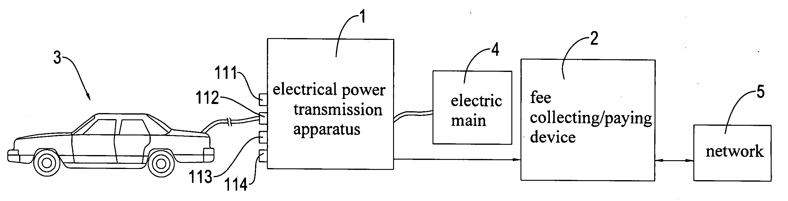
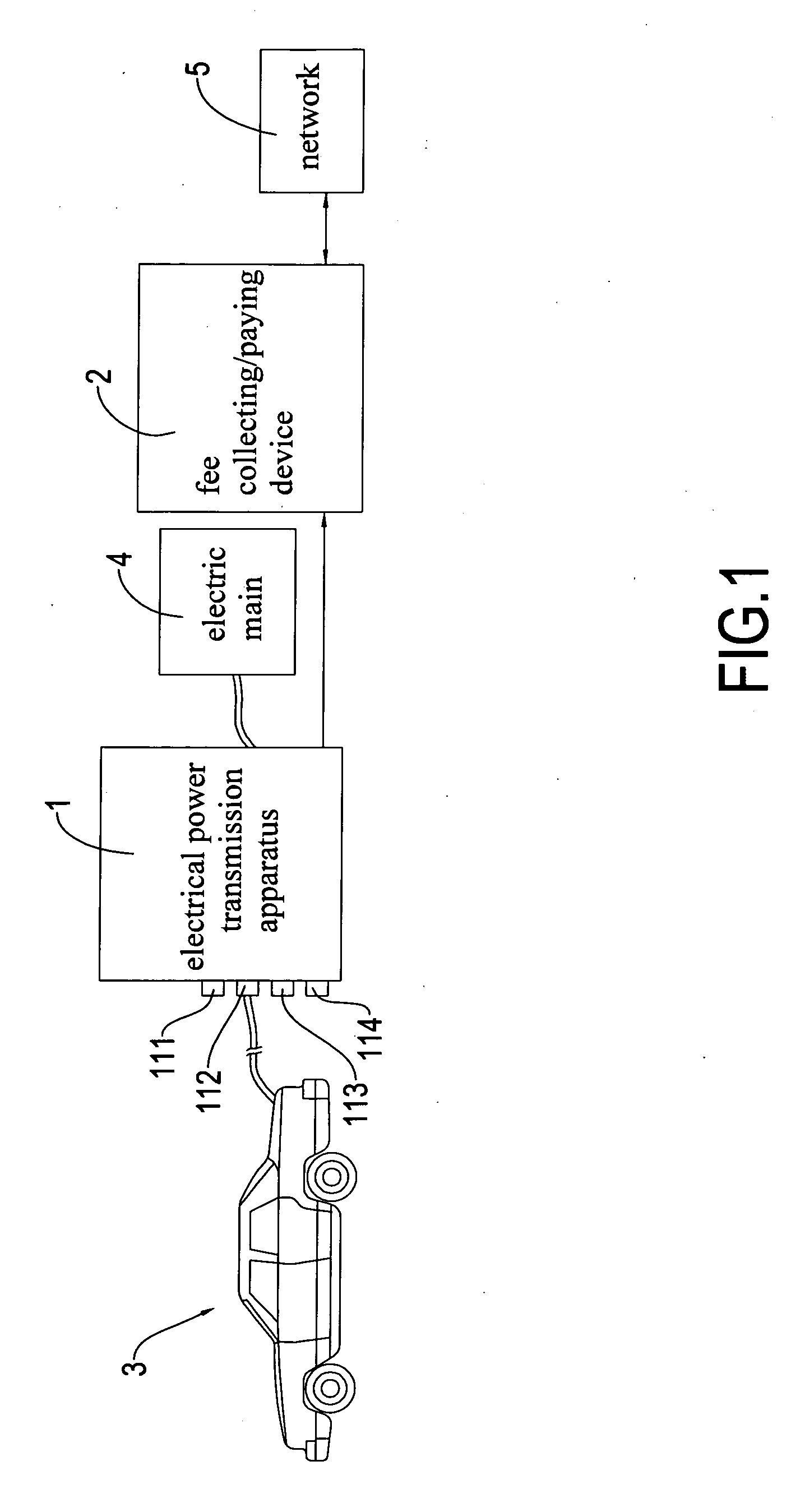
[0021]Referring to FIG. 3, which illustrates a block diagram of the electrical power transmission apparatus 1 in accordance with the present invention that is only operable for selling electrical power, the electrical power transmission apparatus 1 comprises a transmission unit 11, a conversion unit 13, an electrical power flow detector 14, and a processing unit 15. The electrical power transmission apparatus 1 is electrically connected to the electric main 4 as an electrical power supply source and is externally connected to a fee collecting device 21.

[0022]The transmission unit 11 comprises a first output port 111 and a second output port 112. The electrical power flow detector 14 is electrically connected to the electric main 4 whereby the electrical power sold and / or bought can be detected by the electrical power flow detector 14.

[0023]The conversion unit 13 comprises a first converter 131 and a second converter 132 that effect conversion of electrical power (such as conversion ...

second embodiment

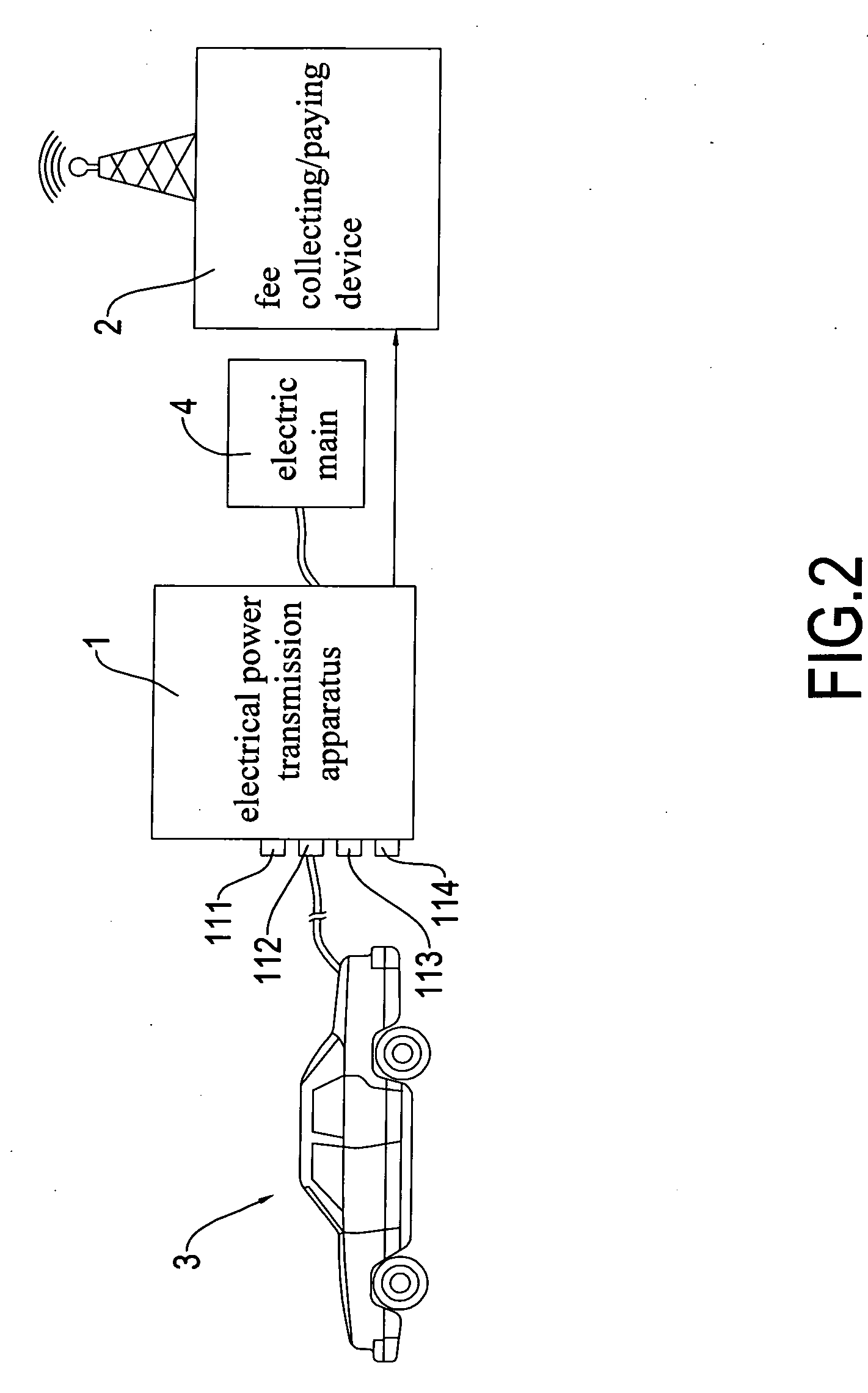
[0027]Referring to a second embodiment illustrated in FIG. 4, the electrical power transmission apparatus 1 may further comprise an automatic anode / cathode switcher 12 and a wireless receiving / transmitting device 16. The automatic anode / cathode switcher 12 is electrically connected between the second output port 112 and the second converter 132, whereby when a user makes a mistake of the polarity in connecting the anode / cathode, the automatic anode / cathode switcher 12 automatically switches the mistaken connection back to the correct connection. Apparently, any sort of suitable fool-proof device may be-alternatively or additionally incorporated to-ensure no mistaken connection of the polarity will be accidentally made by the user. The wireless receiving / transmitting device 16 is electrically connected to the processing unit 15, whereby when system abnormality (such as malfunction and insufficiency of cash) occurs in the processing unit 15 and / or a notification needs to be made, the ...


PUM


Abstract

The electrical power transmission apparatus is electrically connected to an electrical main and a fee collecting device. The electrical power transmission apparatus includes a transmission unit that includes a first output port and a second output port; an electrical power flow detector is electrically connected to the electric main; a conversion unit includes a first converter and a second converter that effect conversion of electrical power, the first and second converters are respectively and electrically connected between the first and second output ports and the electrical power flow detector, and the first and second output ports respectively supply alternate-current (AC) power and direct-current (DC) power through the conversion effected by the first and second converters; and a processing unit is electrically connected between the electrical power flow detector and the fee collecting device and is further electrically connected to the conversion unit to control selection of the electrical power to be transmitted to AC power or DC power. The processing unit receives a detection result of the electrical power flow detected by the electrical power flow detector for generating a related amount of fee with which the fee collecting device carries out a fee collecting operation.

Description

FIELD OF THE INVENTION[0001]The present invention relates to an electrical power transmission apparatus, and in particular to an electrical power transmission apparatus that sells electrical power to all sorts of electricity-operated machines (such as an electrical automobile, an electrical motorcycle, a lawn mower, a lawn removing device, or an electrical saw) or storage battery removed from such electricity-operated machines and that additionally buys electrical power from an external source.BACKGROUND OF THE INVENTION[0002]Since fossil resources provided by the Earth is limited and further due to the global warming issue that we are facing today, locomotive vehicle, such as cars and motorcycles, that are driven by fossil fuel operated engines will be gradually replaced by electrical automobiles and electrical motorcycles.[0003]Although being environmentally friendly, the electrical automobiles and electrical motorcycles do not have a satisfactory duration of operation for each ch...

Claims


Application Information

Patent Timeline
Patent Type & Authority Applications(United States)
IPC IPC(8): H02J7/00
CPCB60L11/1816Y04S30/14B60L11/1846B60L11/1848B60L2210/20G06Q50/06H02J7/0055H02J7/022Y02T10/7005Y02T10/725Y02T90/121Y02T90/127Y02T90/128Y02T90/14Y02T90/163Y02T90/169B60L11/1824Y02T10/7072B60L53/65B60L53/665H02J2207/40H02J7/02H02J2207/20Y02T10/72Y02T90/12Y02T90/167Y02T10/70Y02T90/16
Inventor YEH, MING-HSIANG
Owner YEH MING HSIANG
Why Eureka
Try Eureka