
Magnetic sensor with concentrator for increased sensing range

Inactive Publication Date: 2010-07-29
ALLEGRO MICROSYSTEMS INC
View PDF100 Cites 98 Cited by
  • Summary
  • Abstract
  • Description
  • Claims
  • Application Information

AI Technical Summary

Benefits of technology

[0009]Particular implementations of the invention may provide one or more of the following advantages. Unlike the magnetic flux concentrators of prior solutions, this magnetic flux concentrator can be a stand-alone structure of an adequate geometry that can be placed in close proximity to the magnetic field sensor, either inside or outside of the magnetic field sensor IC package. It can be placed behind the magnetic field sensor IC in an arrangement that does not include a back biasing magnet, thus optimizing the magnetic flux concentration solution for applications with targets that incorporate a magnetic flux source. Also, the use of a magnetic flux concentrator in such configurations causes an increase in magnetic flux concentration, which in turn increases the maximal sensing range over which the magnetic field sensor IC can operate. A target can therefore be placed at a greater distance from the magnetic field sensor IC than would otherwise be possible.

Problems solved by technology

Also, the use of a magnetic flux concentrator in such configurations causes an increase in magnetic flux concentration, which in turn increases the maximal sensing range over which the magnetic field sensor IC can operate.

Method used


Image

  • Magnetic sensor with concentrator for increased sensing range
  • Magnetic sensor with concentrator for increased sensing range
  • Magnetic sensor with concentrator for increased sensing range

Examples


Embodiment Construction

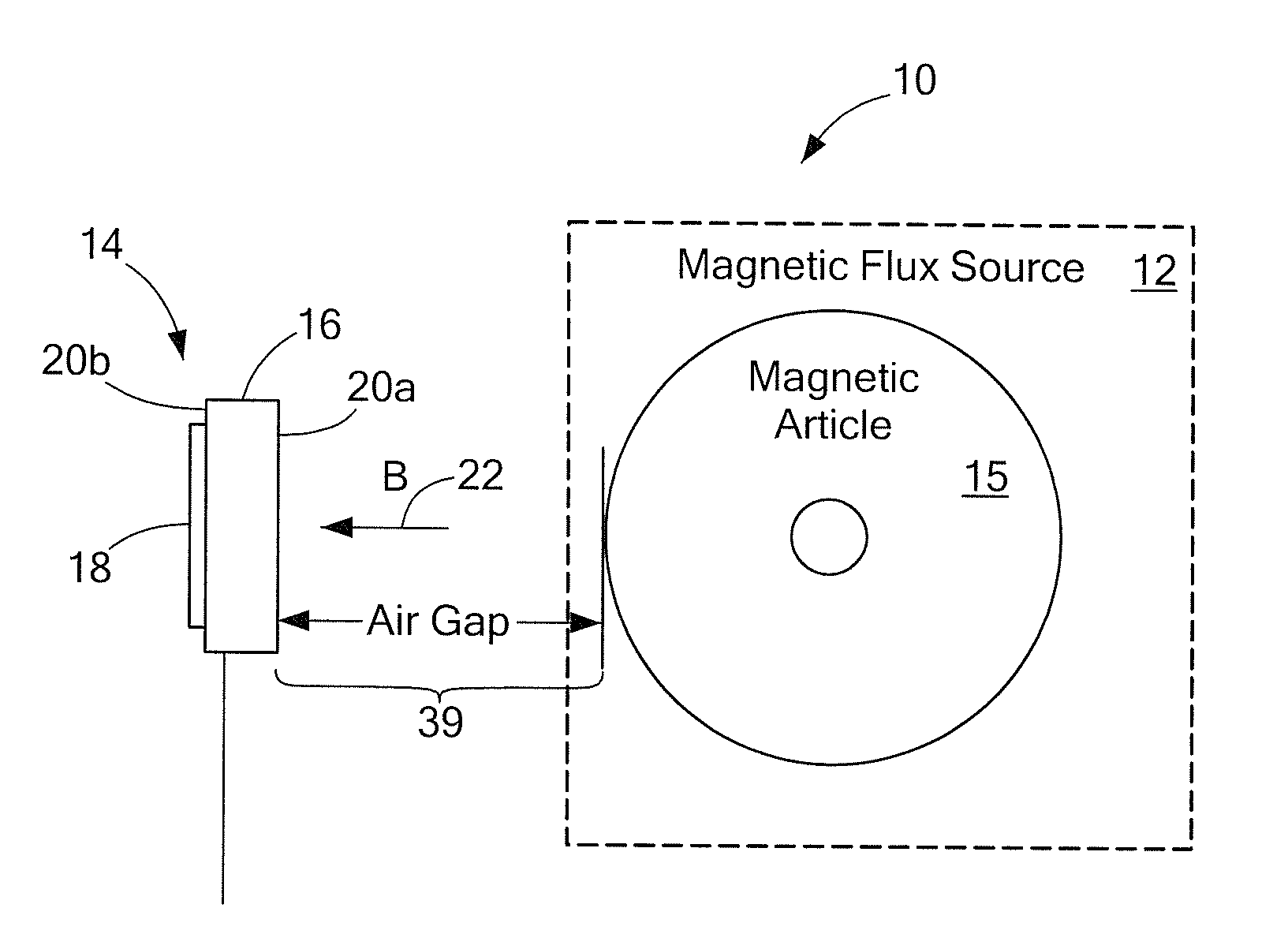
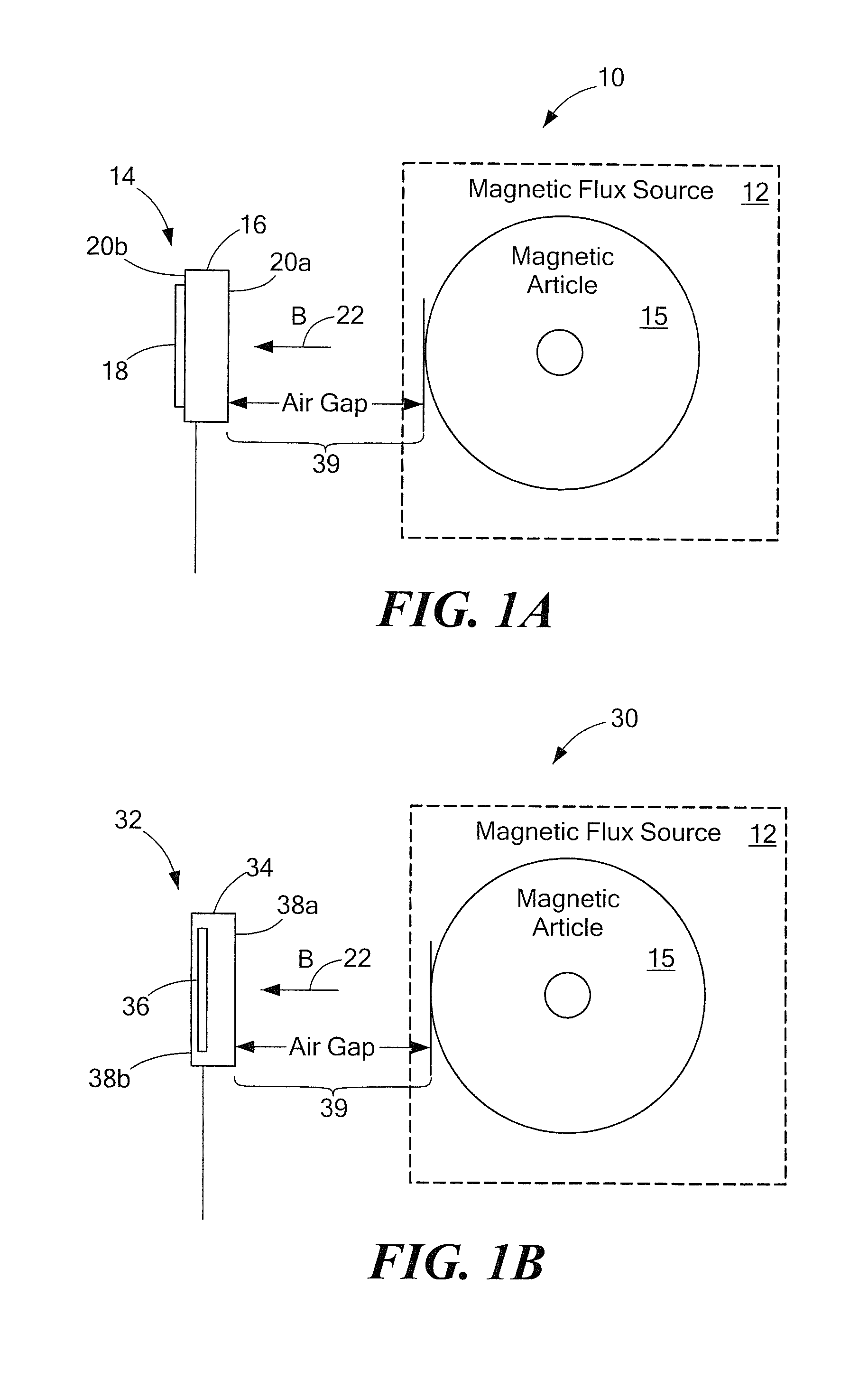
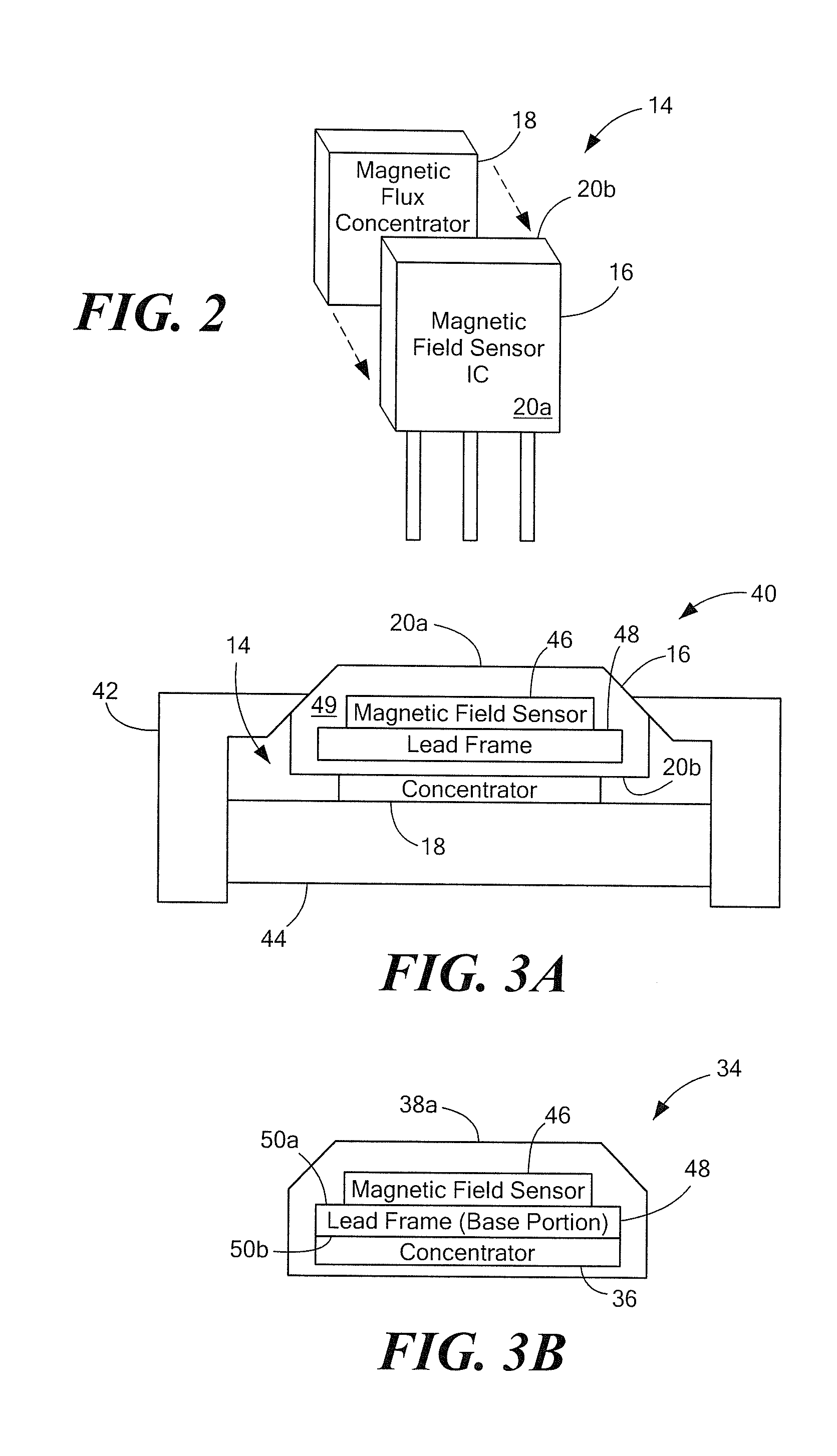
[0016]FIGS. 1A-1B illustrate a magnetic field sensing application that features a magnetic field sensor configured to use a magnetic flux concentrator to increase its sensing range with respect to a magnetic flux source. In one exemplary embodiment, as shown in FIG. 1A, a magnetic field sensing application 10 includes a magnetic flux (or field) source 12 and a sensor 14. The magnetic flux source 12 may be (or may be implemented to include) a magnetic article 15 such as a ring magnet, as shown. The sensor 14 includes a magnetic field sensing device in the form of a magnetic field sensor integrated circuit (“IC”) 16. Also included in the sensor 14 is a magnetic flux concentrator 18 that is disposed proximate to the magnetic field sensor IC 16. The magnetic flux concentrator 18 is externally coupled to or with the magnetic field sensor IC package 16, possibly within a housing, e.g., a plastic canister, of a package sub-assembly (not shown). In one implementation, the magnetic flux conc...


PUM


Abstract

A sensor that includes a magnetic flux concentrator is presented. The sensor includes a sensor integrated circuit with a structure that includes a magnetic field sensor to sense a magnetic field generated by an external magnetic flux source comprising a magnetic article. The stricture has a first surface to face the external magnetic flux source and an opposing second surface. The sensor integrated circuit also includes a lead frame connected to the structure and having a base portion with a first base portion surface to support the stricture and an opposing second base portion surface. Also provided in the sensor is a magnetic flux concentrator to concentrate magnetic flux of the magnetic field. The magnetic flux concentrator can be disposed proximate to the second base portion surface such that the structure and lead frame base portion are located between the magnetic flux concentrator and the external magnetic flux source when the sensor integrated circuit is positioned relative to the external magnetic flux source.

Description

CROSS-REFERENCE TO RELATED APPLICATIONS[0001]Not applicable.STATEMENT REGARDING FEDERALLY SPONSORED RESEARCH[0002]Not applicable.FIELD OF THE INVENTION[0003]This invention relates generally to magnetic field sensors and more particularly, to magnetic field sensors used in conjunction with magnetic flux concentrators.BACKGROUND OF THE INVENTION[0004]The use of magnetic flux concentrators in magnetic field sensing applications is well known. Applications include magnetic field sensors that detect movement, as well as magnetic field sensors that can measure current (“current sensors”).[0005]In some prior sensors with back-biasing permanent magnets, for example, a magnetic flux concentrator is provided between the back-biasing magnet and a sensor integrated circuit (IC). The sensor IC contains at least one active sensing element (such as a Hall-effect element). This type of arrangement is useful in applications like gear tooth sensing applications that involve a ferromagnetic object (e....

Claims


Application Information

Patent Timeline
IPC IPC(8): G01R33/02G01R33/07G01R33/09
CPCG01R33/0005G01R33/072G01R33/0047G01R33/0023
Inventor FOLETTO, ANDREAFRIEDRICH, ANDREAS P.TAYLOR, WILLIAM P.
Owner ALLEGRO MICROSYSTEMS INC
Learn More