Optical module

a technology of optical modules and optical fibers, applied in the field of optical modules, can solve the problems of small absorption in the amplification optical fiber, affecting the refractive index of the optical fiber, and affecting the refractive index of the optical fiber, and achieve the effect of higher refractive index

Inactive Publication Date: 2010-07-29
MEGAOPTO
View PDF7 Cites 41 Cited by
  • Summary
  • Abstract
  • Description
  • Claims
  • Application Information

AI Technical Summary

Benefits of technology

[0012]The present invention has been developed to eliminate the problems described above. It is an object of the present invention to provide an optical module that uses a novel structure for removing pumping light and transporting heat, such that excessive light is heat-transported out of a fiber fused portion with greater efficiency.
[0014]In particular, the fusion splicing structure includes a pumping light removing resin, and a reinforcing member. The pumping light removing resin makes up part or the entirety of a protective sleeve that covers directly the tip portions of the amplification optical fiber and the transmission optical fiber from which the cover resin is removed. The pumping light removing resin has a higher refractive index than the first cladding of the amplification optical fiber. The reinforcing member comprises a material that resists heat shrinkage of the protective sleeve. The reinforcing member is disposed inside the protective sleeve in a state where a portion of the reinforcing member including at least one of the ends thereof, or a portion including both ends, is disposed outside the pumping light removing resin. In such a reinforcing member, heat migrates from a portion covered by the pumping light removing resin (including one end positioned inside the protective sleeve) to a portion exposed from the pumping light removing resin (including the other end). The above configuration allows transporting heat that accumulates in the reinforcing member, through the projecting portion of the reinforcing member that projects beyond the pumping light removing resin and that includes the other end of the reinforcing member.

Problems solved by technology

However, the absorption in the amplification optical fiber is small in case of, for example, single pass configurations.
When the amplification optical fiber is spliced to a transmission optical fiber, failure to dump the pumping light results in heating on account of the surplus pumping light.
Such heating may ignite the cover resins of the transmission optical fiber and the splicing portion.

Method used


Image

  • Optical module
  • Optical module
  • Optical module

Examples


Embodiment Construction

[0039]In the following, embodiments of an optical module according to the present invention will be explained in detail with reference to FIGS. 1 to 3, 4A to 5B, and 6 to 21. In the description of the drawings, identical or corresponding components are designated by the same reference numerals, and overlapping description is omitted.

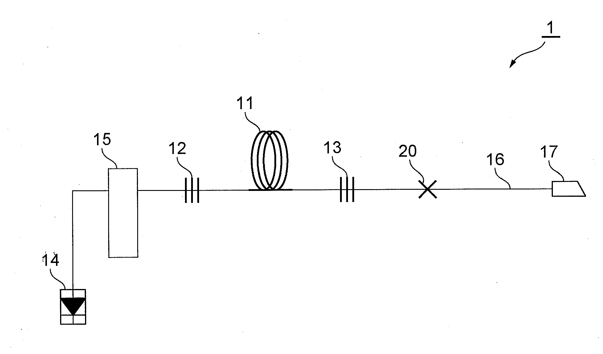
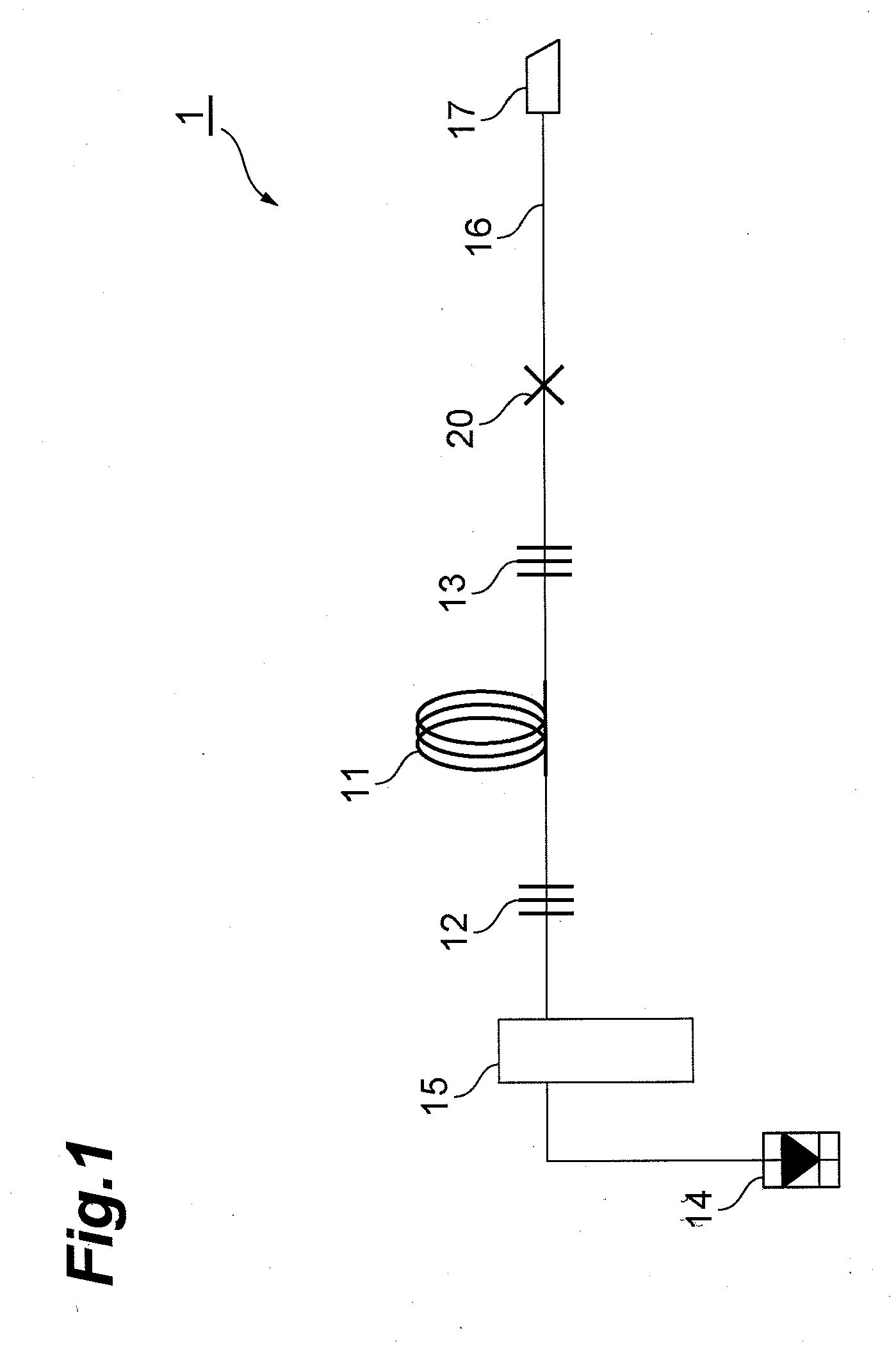
[0040]FIG. 1 is a view showing a configuration example of a resonator-type fiber laser light source. In a fiber laser light source 1 shown in FIG. 1, a laser resonator is made up of reflective units 12, 13 disposed at both ends of an amplification optical fiber 11. The reflective units 12, 13 are constituted by an FBG or a mirror reflector. The pumping light outputted by a pumping light source 14 passes through a combiner 15 and one of the reflective units 12, and is supplied to the amplification optical fiber 11, where it pumps rare earth elements contained in the amplification optical fiber 11. The light emitted by the amplification optical fiber 11 on...


PUM


Abstract

The present invention relates to an optical module having a structure for reducing adverse contingencies such as increased number of fusion splicing points, drops in output, and higher costs associated with a greater number of optical components. The optical module comprises an amplification optical fiber, a transmission optical fiber, and a fusion splicing structure that fusion-splices the amplification optical fiber to the transmission optical fiber, in a state where a cover layer is removed at the tip portions, including the end faces, of these optical fibers. The fusion splicing structure includes a pumping light removing resin that covers directly the tip portions of the amplification optical fiber and the transmission optical fiber from which the cover layer is removed. The pumping light removing resin has a higher refractive index than a first cladding of the amplification optical fiber. The above configuration allows transmitted pumping light, for which the confinement effect by the first cladding of the amplification optical fiber is cancelled, to escape more efficiently out of the fusion splicing portion.

Description

BACKGROUND OF THE INVENTION[0001]1. Field of the Invention[0002]The present invention relates to an optical module comprising an amplification optical fiber and a propagation optical fiber that are spliced to each other.[0003]2. Related Background of the Invention[0004]Recent years have witnessed growing interest in processing technologies that use laser light, and therefore the need for high-output laser light sources is ever greater in a wide variety of fields such as machinery manufacture, medicine and the like. Laser light sources that have been the focus of particular attention include fiber laser light sources, which use an amplification optical fiber, doped with rare earth elements such as Yb, Er, Tm and the like, as an amplification medium. In such fiber laser light sources, high-output laser light can be created within an amplification optical fiber by supplying pumping light to the amplification optical fiber, which is disposed inside a resonator structure. Fiber laser lig...

Claims


Application Information

Patent Timeline
Patent Type & Authority Applications(United States)
IPC IPC(8): H01S3/00G02B6/255H01S3/067H01S3/10
CPCG02B6/2551H01S3/0675H01S3/1618H01S3/094007H01S3/06754
Inventor TAMAOKI, SHINOBU
Owner MEGAOPTO
Why Eureka
Try Eureka