Heat Radiation Mechanism of Electronic Apparatus and Electronic Apparatus

a radiation mechanism and electronic equipment technology, applied in the direction of electrical equipment casings/cabinets/drawers, cooling/ventilation/heating modifications, instruments, etc., can solve the problems of disadvantageous difficulty in effectively radiating disadvantageous difficulty in cooling, etc., to effectively radiate reduce the density of the air warmed by the heat generated by the heating device, and suppress the diffusion of air into the housing

Inactive Publication Date: 2010-07-29
FUNAI ELECTRIC CO LTD
View PDF34 Cites 6 Cited by
  • Summary
  • Abstract
  • Description
  • Claims
  • Application Information

AI Technical Summary

Benefits of technology

[0009]In the heat radiation mechanism of the electronic apparatus according to the first aspect, as hereinabove described, the air flow route allowing flow of air between the first vent hole and the second vent hole is formed by the first duct and the second duct, at least the portion mounted with the heating device of the circuit board is arranged in the air flow route, and the opening allowing flow of air between the first duct side and the second duct side is formed on the portion mounted with the heating device of the circuit board in the air flow route, and heat generated from the heating device is radiated from the first vent hole or the second vent hole through the air flow route. Thus, the cold air sucked from one of either the first vent hole or the second vent hole passes through the air flow route and the opening to be guided to the portion mounted with the heating device of the circuit board, and hence the heating device is cooled by the cold air. Consequently, the density of the air warmed by the heat generated from the heating device is reduced, the air becomes the rising air, the warmed air can be discharged (radiated) to the outside from the other of either the first vent hole or the second vent hole, and hence the heat generated from the heating device can be effectively radiated.
[0027]In the aforementioned electronic apparatus according to the second aspect, a portion of the first duct on the circuit board side and a portion of the second duct on the circuit board side are preferably arranged to be in close contact with each other in a state of holding the portion mounted with the heating device of the circuit board therebetween. According to this structure, air sucked from one of either the first duct or the second duct is difficult to leak from a boundary between the first and second ducts into the housing, and hence diffusion of the sucked air into the housing can be suppressed. Thus, the heat generated from the heating device can be more effectively radiated.

Problems solved by technology

In the heat radiation mechanism of the electronic apparatus disclosed in the aforementioned Japanese Patent Laying-Open No. 2003-174276, however, the cold air sucked from the vent hole inlet is diffused in the housing and hence the heating device is disadvantageously difficult to be cooled.
Thus, the heat generated from the heating device is disadvantageously difficult to be effectively radiated.

Method used


Image

  • Heat Radiation Mechanism of Electronic Apparatus and Electronic Apparatus
  • Heat Radiation Mechanism of Electronic Apparatus and Electronic Apparatus
  • Heat Radiation Mechanism of Electronic Apparatus and Electronic Apparatus

Examples


first embodiment

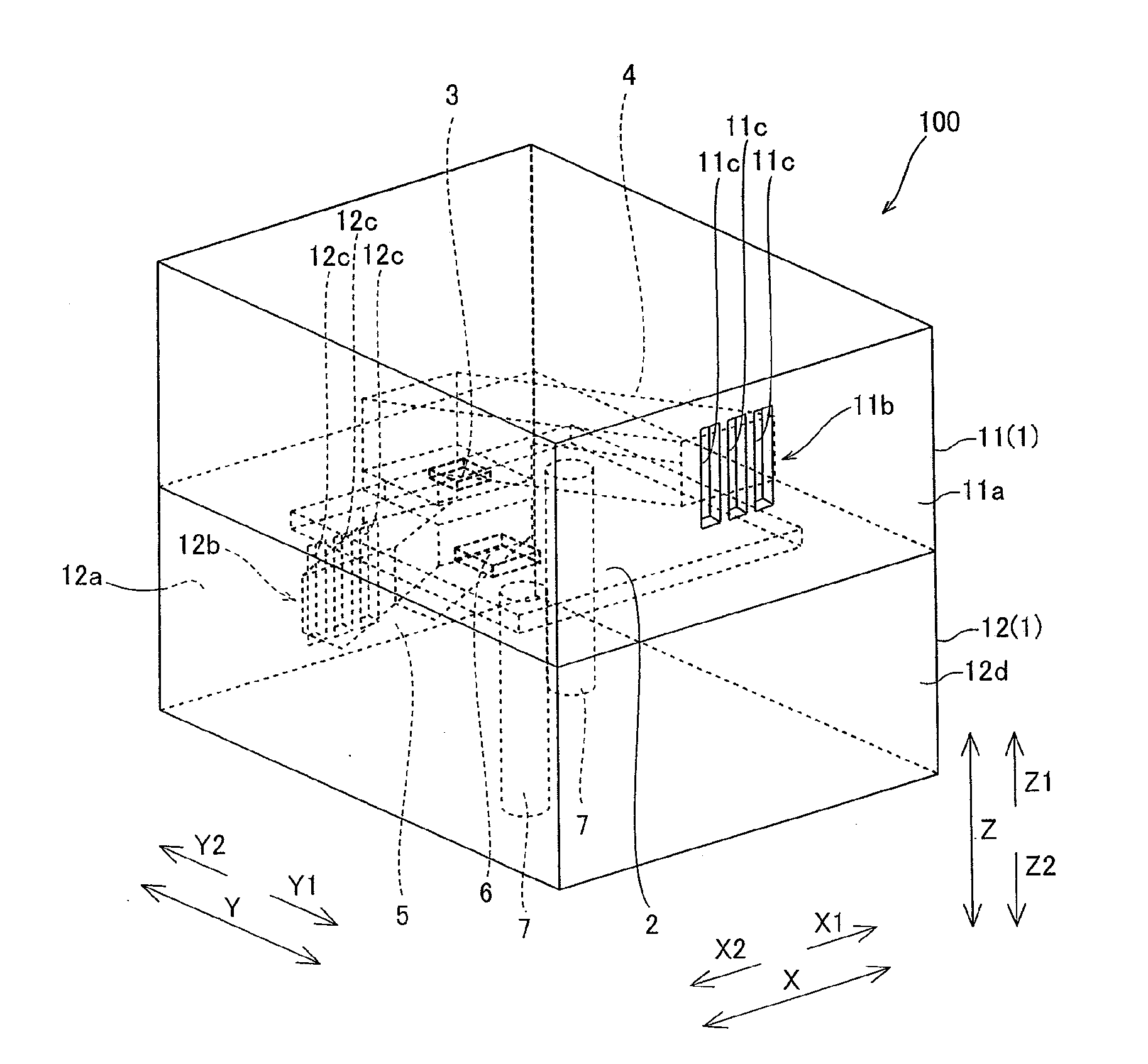
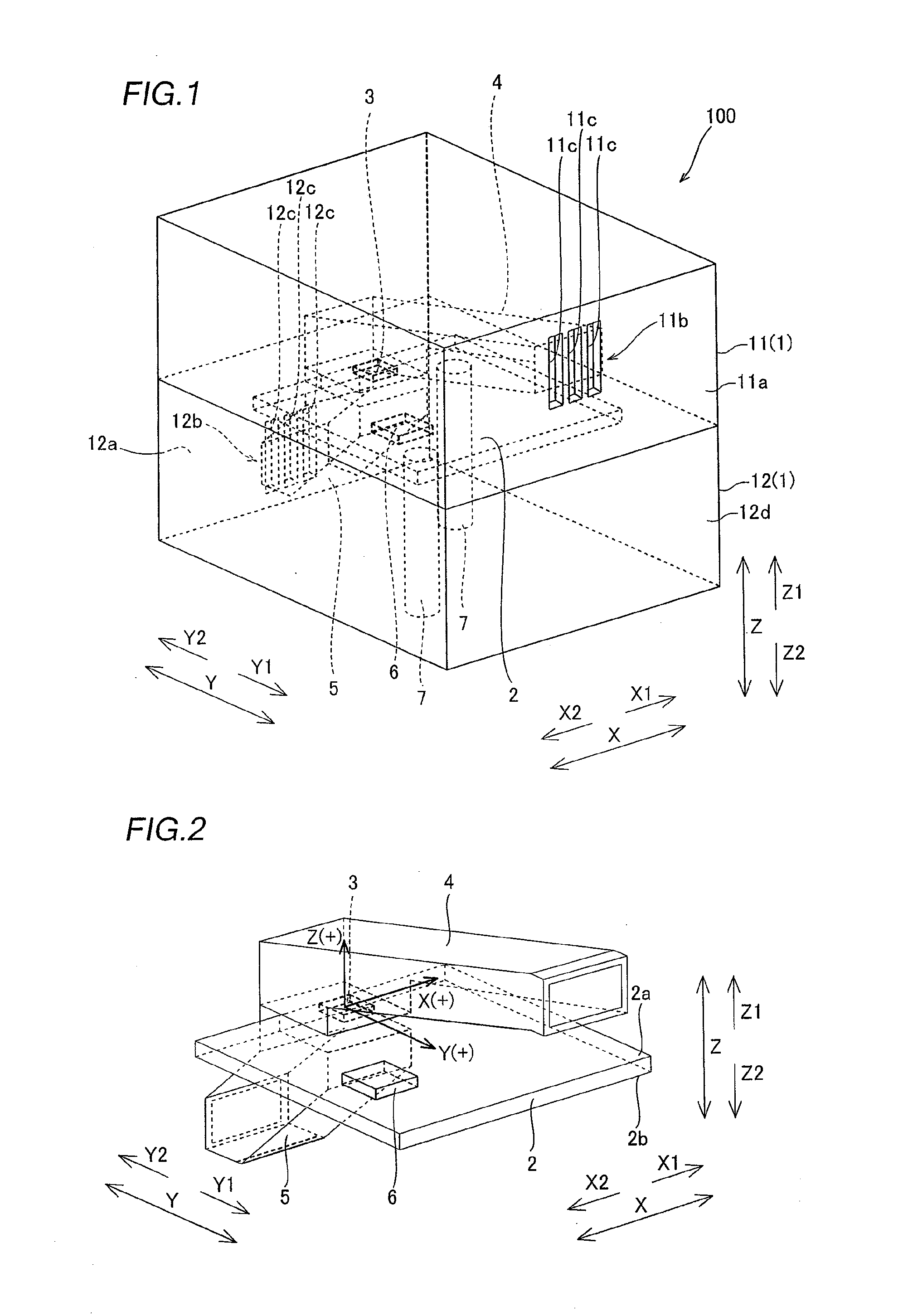
[0048]A structure of a heat radiation mechanism of an electronic apparatus 100 according to the first embodiment of the present invention will be described with reference to FIGS. 1 to 9.

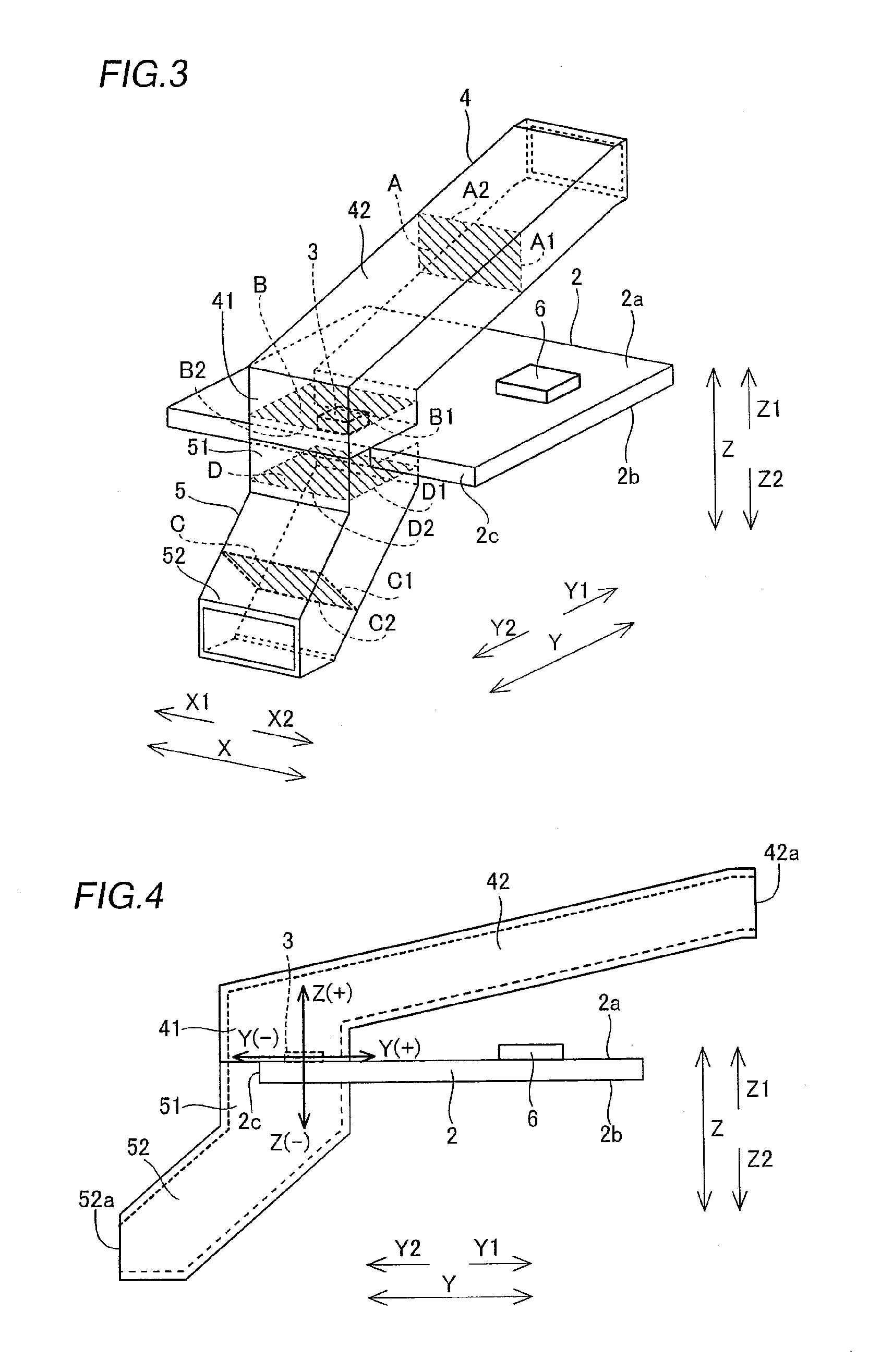
[0049]As shown in FIGS. 1 to 4, the heat radiation mechanism of the electronic apparatus 100 according to the first embodiment of the present invention comprises a housing 1, a circuit board 2 mounted in the housing 1, a heating device 3 mounted on the circuit board 2, a first duct 4 arranged above the heating device 3, a second duct 5 arranged below the heating device 3, a device 6 other than the heating device 3 arranged on the circuit board 2, and board support portions 7 supporting the circuit board 2.

[0050]The housing 1 of the electronic apparatus 100 includes an upper housing 11 and a lower housing 12. A first vent hole 11b is formed on a side surface (outer surface) 11a of the upper housing 11. This first vent hole 11b includes rectangular three slits 11c extending in a direction Z, as shown ...

second embodiment

[0074]Referring to FIGS. 10 to 14, in a structure of a heat radiation mechanism of an electronic apparatus 100a according to a second embodiment of the present invention, in a case where an X-axis, a Y-axis and a Z-axis orthogonal to each other are considered assuming that a center of a heating device 3 is an origin, a first vent hole 110b is provided on plus direction sides of the X-, Y- and Z-axes, while a second vent hole 120b is provided on minus direction sides of the X-, Y- and Z-axes, dissimilarly to the aforementioned first embodiment.

[0075]In the heat radiation mechanism of the electronic apparatus 100a according to the second embodiment of the present invention, four leg portions 106 for spacing a side surface 110a and a side surface 120d on a side mounted with a housing 101 from a surface mounted with the housing 101 are provided on a side surface (outer surface) 110a formed with the first vent hole 110b of an upper housing 110 and a side surface (outer surface) 120d of a...

third embodiment

[0090]Referring to FIGS. 18 to 20, in a structure of a heat radiation mechanism of an electronic apparatus 100b according to a third embodiment of the present invention, an air flow hole 21 allowing flow of air is provided in the vicinity of a region mounted with a heating device 3 of a circuit board 2 dissimilarly to the aforementioned second embodiment.

[0091]In the heat radiation mechanism of the electronic apparatus 100b, the heating device 3 is mounted in the vicinity of a center of the circuit board 2, as shown in FIGS. 18 and 19. The one air flow hole 21 is provided on the region mounted with the heating device 3 of the circuit board 2 arranged in an air flow route constituted by a first duct 204 and a second duct 205, so that an opening allowing flow of air between the first duct 204 side and the second duct 205 side is formed. This one air flow hole 21 is formed in a substantially rectangular shape in plan view.

[0092]As shown in FIG. 20, the circuit board 2 is set on a bound...


PUM


Abstract

In a heat radiation mechanism of an electronic apparatus, an opening allowing flow of air between a first duct side and a second duct side is formed on a portion mounted with a heating device of a circuit board in an air flow route constituted by a first duct and a second duct, and heat generated from the heating device is radiated from a first vent hole or a second vent hole through the air flow route.

Description

BACKGROUND OF THE INVENTION[0001]1. Field of the Invention[0002]The present invention relates to a heat radiation mechanism of an electronic apparatus and an electronic apparatus, and more particularly, it relates to a heat radiation mechanism of an electronic apparatus and an electronic apparatus each comprising vent holes for radiating heat generated from a heating device.[0003]2. Description of the Background Art[0004]In general, a heat radiation mechanism of an electronic apparatus comprising a vent hole for radiating heat generated from a heating device is disclosed in Japanese Patent Laying-Open No. 2003-174276, for example.[0005]The aforementioned Japanese Patent Laying-Open No. 2003-174276 discloses a heat radiation mechanism of an electronic apparatus comprising a housing including an upper housing and a lower housing, a circuit board arranged in the housing, and a heating device mounted on the circuit board. A vent hole inlet for sucking air is formed on a bottom surface o...

Claims


Application Information

Patent Timeline
Patent Type & Authority Applications(United States)
IPC IPC(8): H05K7/20F28D15/00
CPCH05K7/20127
Inventor YAMAGIWA, DAISUKE
Owner FUNAI ELECTRIC CO LTD
Why Eureka
Try Eureka