Skin Tensioner for Hair Transplantation

a skin tensioner and hair technology, applied in the field of skin tensioners for hair transplantation, can solve the problems of difficult to remove, difficult to apply, and difficult to remove retraction, etc., and achieve the effect of easy removal, easy removal, and easy application

Active Publication Date: 2010-07-29
VENUS CONCEPT INC
View PDF33 Cites 80 Cited by
  • Summary
  • Abstract
  • Description
  • Claims
  • Application Information

AI Technical Summary

Benefits of technology

[0006]The present application discloses various skin or body surface tensioning devices and methods that may be applied to a scalp, skin or other body surface area during various medical, cosmetic, or dermatological procedures. Such devices are especially useful, for example, when harvesting and / or implanting hair follicles or follicular units (FUs). In certain embodiments, the skin tensioning devices enable monitoring of the magnitude of the tension applied to the skin, and adjustment thereto if necessary. Furthermore, the tensioning devices disclosed are relatively easy to apply by one person or one hand, and may be easy to remove and reapply. Thus, the devices may be easily removed from the treatment area to allow the patient to get up and move around in the middle of the procedure if desired. Another advantage of various embodiments described herein is that the skin may be placed under substantially uniform or even tension across a treatment area. The devices may be relatively inexpensive to manufacture and certain parts may be disposable to facilitate cleanup and remit reuse of easy to sterilize components. Further, the device may be provided with the ability to suction away blood and flush with saline. In addition the device may be provided with suction to more securely hold the skin tensioning device against the body surface. In combination with an imaging system, the tensioning device may provide a platform for fiducials.

Problems solved by technology

Hair transplantation is very labor-intensive and complex procedure that requires skill and precision.
These retractors, however, are not very suitable for skin tensioning required for procedures, such as hair transplantation.

Method used


Image

  • Skin Tensioner for Hair Transplantation
  • Skin Tensioner for Hair Transplantation
  • Skin Tensioner for Hair Transplantation

Examples


Embodiment Construction

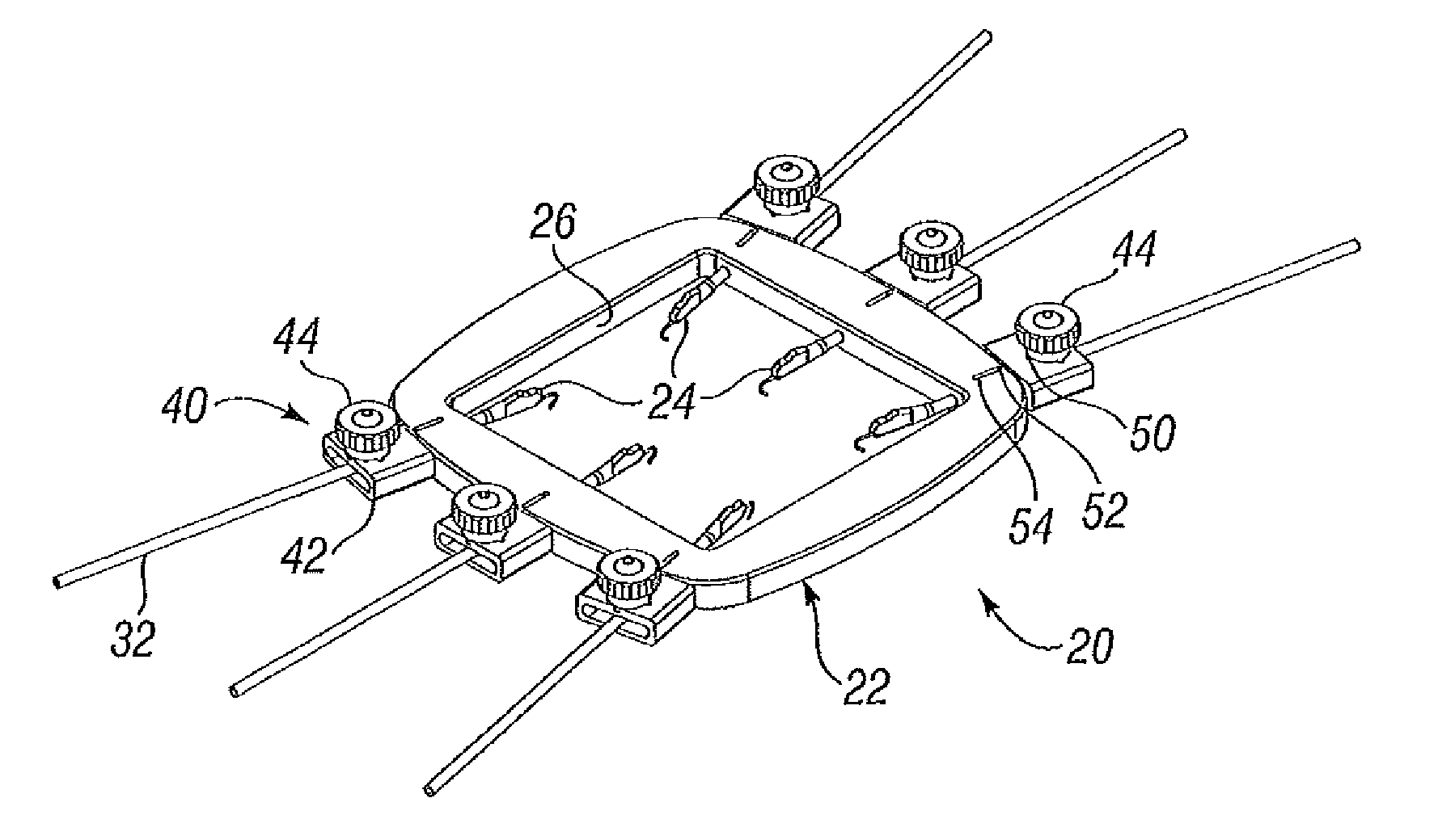
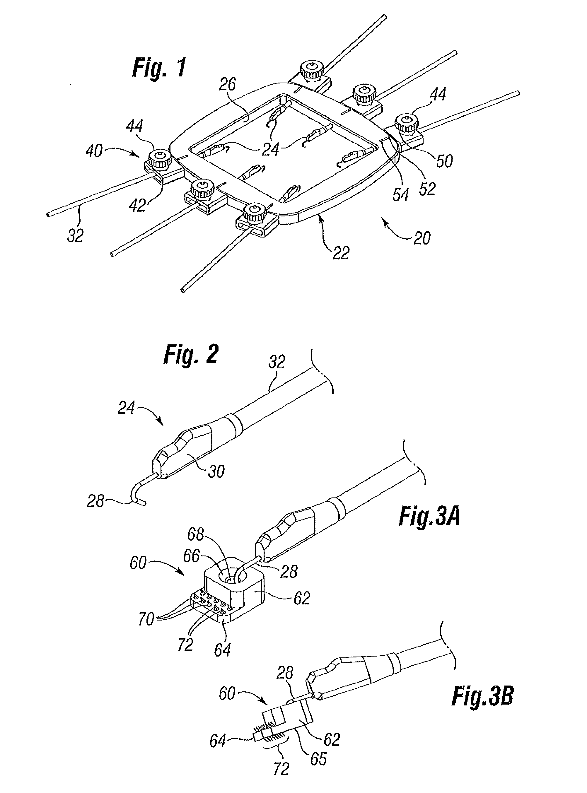
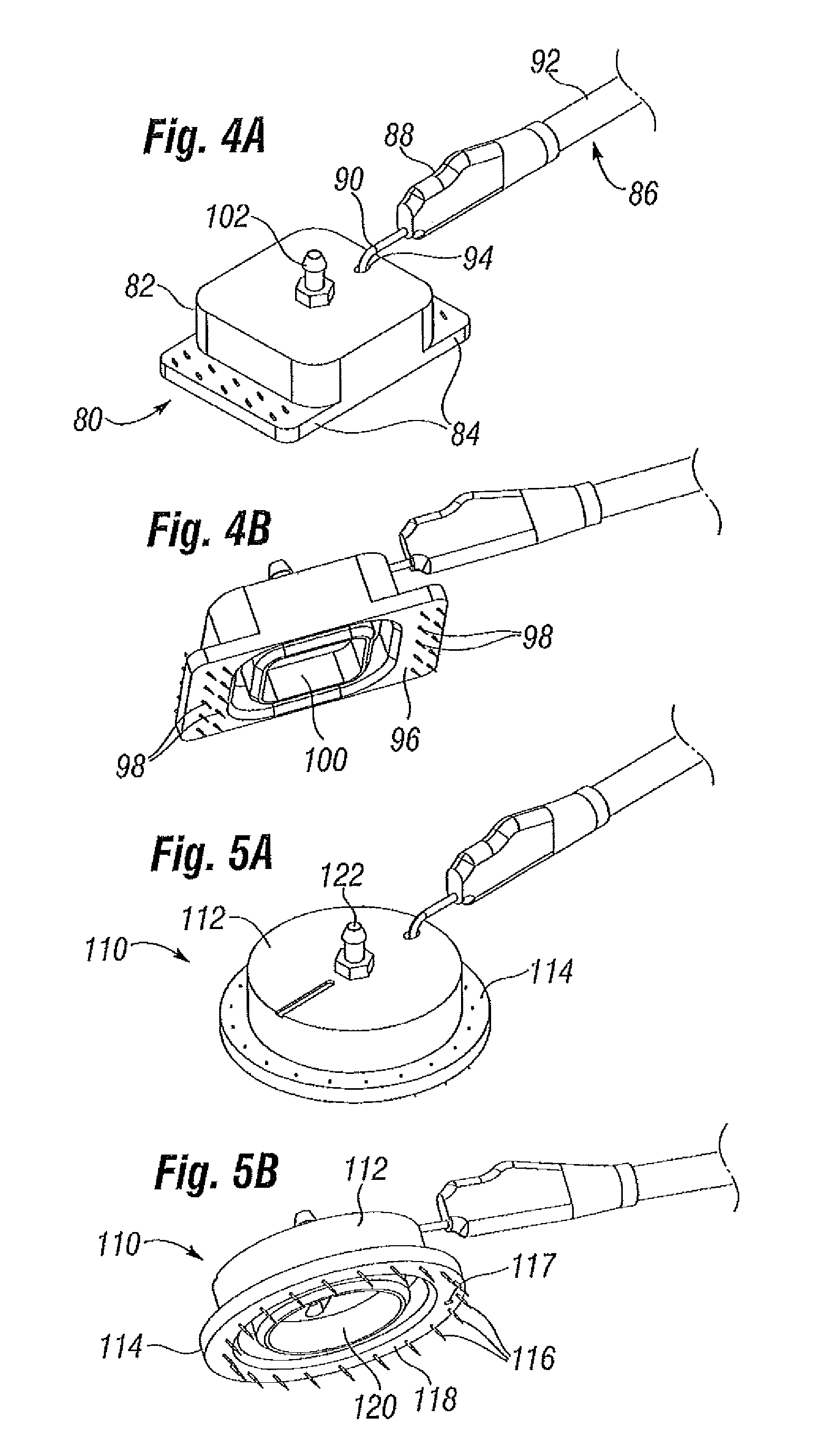
[0034]In the following Detailed Description reference is made to the accompanying drawings that show by way of illustration specific embodiments in which the invention may be practiced. In this regard, directional terms, such as “top,”“bottom,”“front,”“back,”“side”, “distal,”“proximal,” etc., are used with reference to the orientation of the Figure(s) being described. Because components or embodiments of the present invention can be positioned in a number of different orientations, the directional terminology is used for purposes of illustration and is in no way limiting. It is to be understood that other embodiments may be utilized and structural or logical changes may be made without departing from the scope of the present invention. The following Detailed Description, therefore, is not to be taken in a limiting sense, and the scope of the present invention is defined by the appended claims.

[0035]It has been found that commercially available surgical retractors, such as that manuf...


PUM


Abstract

Devices and methods for applying tension to an area of skin, in particular for follicular unit removal and implant in a hair transplantation procedure are provided. The devices may include a frame with at least two skin contact members that hold to the skin. Also disclosed are various ways to apply a force displacing the skin contact members apart, thus creating tension in the skin therebetween. The devices and methods may incorporate suction that helps the skin contact members securely hold to the skin. Barbs or microbarbs also may be used to help secure the skin contact members to the skin. The frame may surround the skin area with tensile forces applied outward in multiple directions, or the frame may be a bifurcated pair of fingers that applies tension substantially uni-directionally. Adjusting members and indicators may be provided to control and display the magnitude of tensile force applied to skin. The tensioning devices and methods may be incorporated into a robotic hair transplantation system.

Description

RELATED APPLICATIONS[0001]This application claims priority under 35 U.S.C. 119(e) to U.S. Provisional Application No. 61 / 146,872 filed Jan. 23, 2009, entitled “SKIN TENSIONER FOR HAIR TRANSPLANTATION”.FIELD OF THE INVENTION[0002]The present invention relates generally to devices, systems and methods for applying tension to an area of skin or a body surface and, in particular, skin tensioners and methods of use in conjunction with hair transplantation procedures.BACKGROUND OF THE INVENTION[0003]There are numerous surgical, cosmetic, therapeutic and dermatological procedures that involve maneuvering an area of skin. Hair transplantation is one of those procedures and it typically involves harvesting donor hair grafts from the “donor areas,” and implanting them in a bald area (“recipient area”). There are various known tools and instruments used for harvesting and implantation of the follicular units (“FUs”), including various needles, punches, and forceps. Hair transplantation is very...

Claims


Application Information

Patent Timeline
Patent Type & Authority Applications(United States)
IPC IPC(8): A61B17/34A61B17/00
CPCA61B17/0206A61B17/0293A61B19/2203A61B19/24A61B17/20A61B2017/0287A61B2017/308A61B2019/464A61B2019/4836A61B2017/00752A61B34/30A61B90/02A61B2090/064A61B2090/0807A61B17/02A61F2/10
Inventor OOSTMAN, JR., CLIFFORD A.JAKUBOWSKI, STEVEN E.
Owner VENUS CONCEPT INC
Why Eureka
Try Eureka