Process and systems

Inactive Publication Date: 2010-08-05
AL MAYAHI ABDULSALAM +1
View PDF24 Cites 81 Cited by
  • Summary
  • Abstract
  • Description
  • Claims
  • Application Information

AI Technical Summary

Benefits of technology

[0128]Thus, in accordance with an embodiment of this aspect of the present invention, a hydraulic Energy Recovery Turbine together with a heat exchanger are used in conjunction for an ammonia-water heat engine (power plant) instead of the conventional pump that is commonly used to pump the working fluid from the condenser (absorber) to the boiler (evaporator). The advantage of using a heat exchanger in conjunction with a hydraulic Turbo Charger (Energy Recovery Turbine) is that it minimises the heat losses through the mixing process between the contents of the boiler (evaporator) and the condenser (absorber). This Mayahi cycle can utilize any available energy sources for heating the evaporator (boiler) with a te

Problems solved by technology

Using such a high-pressure process will have an impact on the cost because of the highly costly pressure pumps required and operating costs to run the

Method used


Image

  • Process and systems
  • Process and systems
  • Process and systems

Examples


Example

[0144]Various aspects of the present invention will now be described by way of example only. These are not the only ways that the invention can be put into practice, but they are the best ways currently known to the applicant.

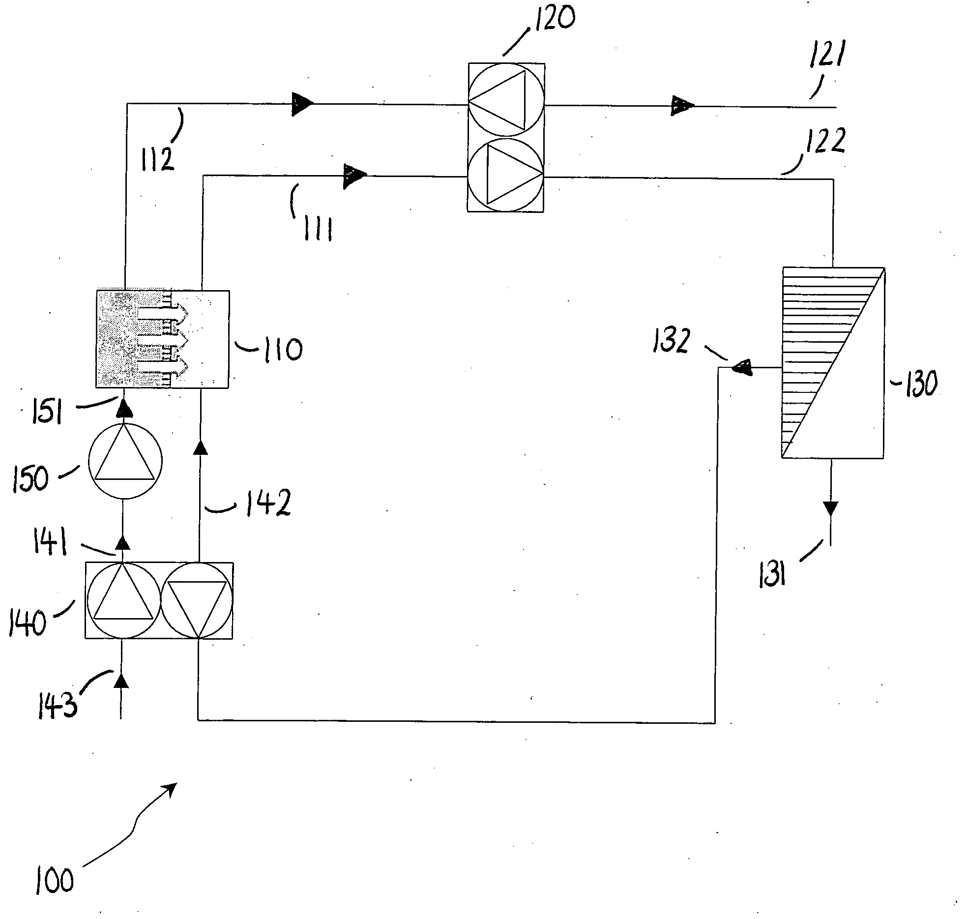
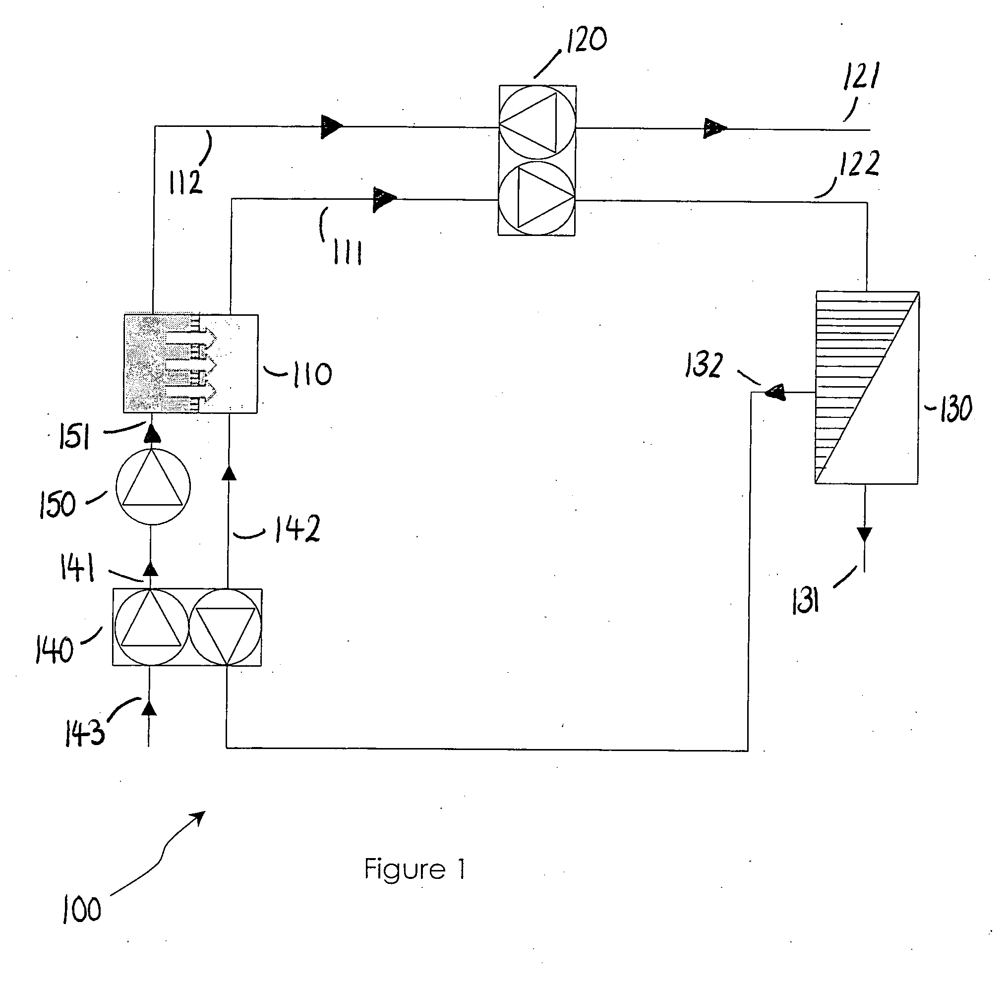
[0145]Referring to FIG. 1, this illustrates a solvent removal apparatus 100. A manipulated Osmosis MO unit 110 has two different concentration solutions separated by a semi-permeable membrane (selective membrane). Pumped seawater or brackish water at a high pressure enters unit 110 via line 151 and leaves via line 112 after losing some of its water, which passes through the membrane to the manipulated solution which has less osmotic pressure (less salt concentration). The concentrated high pressure stream 112 enters an energy recovery turbine 120, and in the process transferring its hydraulic energy, and leaves via line 121 as a rejected effluent. The diluted manipulated solution leaves 110 via line 111 to enter unit 120 gaining hydraulic energy and leaves at h...


PUM


Abstract

An apparatus for recovering energy from an osmotic system, said apparatus comprising: (i) a feed stream (143,251); (ii) pressure means (140,150, 250, 254) to pressurise said feed stream; (iii) a manipulated osmosis unit (110,220,230); (iv) an energy recovery unit (120, 240, 260) in fluid connection with second solution side of the manipulated osmosis unit; (v) a reverse osmosis unit (130) receiving a feed from the energy recovery unit.

Description

FIELD OF THE INVENTION[0001]The present invention relates to methods and apparatus for a solvent removal process by a pressure driven process at lower applied pressure utilizing Manipulated Osmosis (MO) and Reverse Osmosis (RO) combined with Energy Recovery Devices (ERD), to methods and apparatus for osmotic energy recovery utilizing Energy Recovery Turbines with forward osmosis units, and to methods and apparatus for transforming energy from a heat source into a usable form using a working fluid such as ammonia—water that is expanded and regenerated. Embodiments of this invention further relate to a method and apparatus for improving the heat utilization efficiency of a thermodynamic cycle. The present invention utilizes an Energy Recovery Turbine, which is an Energy Recovery Device (ERD), in the cycle to maintain the working fluid, for example ammonia-water solution at a similar level of concentration) between the evaporator (boiler) and the condenser (absorber) by linked them tog...

Claims


Application Information

Patent Timeline
IPC IPC(8): F01K25/10C02F1/44
CPCB01D61/002B01D61/022B01D61/06B01D2313/246B01D2317/025F03G7/04C02F2103/08C02F2201/009F01K25/06F03G7/005C02F1/441Y02W10/37Y02A20/131Y02A20/212B01D61/026F03G7/015F03G4/035
Inventor AL-MAYAHI, ABDULSALAMALJOHANI, MOHAMMED S.
Owner AL MAYAHI ABDULSALAM
Why Eureka
Try Eureka