Multistage hollow tube-drawing machine

The technology of a hollow extubation machine and a secondary cylinder, which is applied in the direction of a lifting device and the like, can solve the problems of a hoist pulling system that is cumbersome, reduces the efficiency of recovery, and has a lot of preparation work, and achieves improved portability, improved stability, and is easy to move. Effect

Inactive Publication Date: 2015-09-30
湖南仪纬科技有限公司
View PDF0 Cites 0 Cited by
  • Summary
  • Abstract
  • Description
  • Claims
  • Application Information

AI Technical Summary

Problems solved by technology

In the actual operation process, since the effective stroke of the cylinder is only 0.5m, the extubation column needs to go through multiple cycles, and the double cylinder structure has disadvantages in terms of high-pressure liquid demand, stability control of the pulling process, and equipment weight control
[0005] To recover pillars in the mine stope, the torque of the hoist can be converted into the pulling force for pulling out the metal pipe by means of the hoist through components such as anchor rods and pulleys. Reduced recycling efficiency

Method used


Image

  • Multistage hollow tube-drawing machine
  • Multistage hollow tube-drawing machine
  • Multistage hollow tube-drawing machine

Examples


Embodiment 1

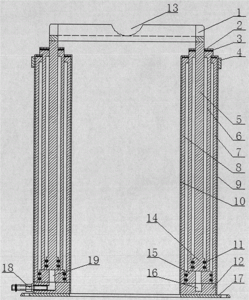
[0019] A multi-stage hollow extubation machine, such as figure 1 As shown, it includes top plate 1, small cover plate 2, gasket 3, outer hoop 4, third-stage cylinder body 5, third-stage cylinder body base 14, second-level cylinder body 6, second-level cylinder body base 15, first-stage cylinder body Outer ring 7, primary cylinder inner ring 8, jacket 9, lining 10, sealing ring 11, primary cylinder base 12, groove 13, main body base 17, oil delivery tank 16, oil delivery hole 19, quick connector 18. An annular cavity is formed between the first-stage cylinder block, the second-stage cylinder block, and the third-stage cylinder block, and is connected with the mobile hydraulic station through the quick joint 18; The oil tank 16 and the oil delivery hole 19 of the secondary cylinder base enter the annular cavity; the outer hoop 4, the outer jacket 9, the inner lining 10, and the main body base 17 maintain the overall stability of the extubation machine. The top plate 1 is a who...

Embodiment 2

[0022] A multi-stage hollow extubation machine, such as figure 1 As shown, it includes top plate 1, small cover plate 2, gasket 3, outer hoop 4, third-stage cylinder body 5, third-stage cylinder body base 14, second-level cylinder body 6, second-level cylinder body base 15, first-stage cylinder body Outer ring 7, primary cylinder inner ring 8, jacket 9, lining 10, sealing ring 11, primary cylinder base 12, groove 13, main body base 17, oil delivery tank 16, oil delivery hole 19, quick connector 18. An annular cavity is formed between the first-stage cylinder block, the second-stage cylinder block, and the third-stage cylinder block, and is connected with the mobile hydraulic station through the quick joint 18; The oil tank 16 and the oil delivery hole 19 of the secondary cylinder base enter the annular cavity; the outer hoop 4, the outer jacket 9, the inner lining 10, and the main body base 17 maintain the overall stability of the extubation machine. The top plate 1 is a who...

Embodiment 3

[0025] A multi-stage hollow extubation machine, such as figure 1 As shown, it includes top plate 1, small cover plate 2, gasket 3, outer hoop 4, third-stage cylinder body 5, third-stage cylinder body base 14, second-level cylinder body 6, second-level cylinder body base 15, first-stage cylinder body Outer ring 7, primary cylinder inner ring 8, jacket 9, lining 10, sealing ring 11, primary cylinder base 12, groove 13, main body base 17, oil delivery tank 16, oil delivery hole 19, quick connector 18. An annular cavity is formed between the first-stage cylinder block, the second-stage cylinder block, and the third-stage cylinder block, and is connected with the mobile hydraulic station through the quick joint 18; The oil tank 16 and the oil delivery hole 19 of the secondary cylinder base enter the annular cavity; the outer hoop 4, the outer jacket 9, the inner lining 10, and the main body base 17 maintain the overall stability of the extubation machine. The top plate 1 is a who...


PUM


Abstract

The invention relates to a hollow tube-drawing machine and designs the machine according to the hydraulic principle to solve the problems such that the existing tube-drawing equipment is heavy, short in stroke and low in recovery rate. The hollow tube-drawing machine mainly comprises a top disc 1, a small cover plate 2, a sealing gasket 3, an outer hoop 4, a tertiary cylinder block 4, a tertiary cylinder block base 14, a secondary cylinder block 6, a secondary cylinder block base 15, a primary cylinder block outer ring 7, a primary cylinder block inner ring 8, a jacket 9, a lining 10, a sealing ring 11, a primary cylinder block base 12, a cavity 13, a main base 17, an oil transfer channel 16, oil transfer holes 19, and a quick connector 18. The hollow tube-drawing machine is light and speedy, convenient to move and simple to operate, allows valuable tubular objects to be recovered efficiently, easily and safely, allows labor to be less intensive for workers and helps improve labor efficiency.

Description

technical field [0001] The invention belongs to the technical field of mechanical equipment, and in particular relates to a multi-stage hollow pipe pulling machine, which is suitable for recovering pillars in mine stopes, recovering steel pipes wedged into the ground at civil and construction foundation sites, steel pipe guardrails in road traffic engineering, and temporary lifting Heavy objects etc. Background technique [0002] Metal pipes are used to maintain the safety of stope roof operation in the mining production process of mine access roads. A large number of metal pipes are used to isolate construction sites in foundation construction sites and traffic engineering, and a large number of metal pipes need to be recycled. [0003] In open-air construction sites, truck cranes are generally relied on to recover metal pipes, but temporary rental of truck cranes is time-consuming and labor-intensive, and the rent is high, so they cannot be on standby for a long time. On ...

Claims


Application Information

Patent Timeline
Patent Type & Authority Applications(China)
IPC IPC(8): B66F11/00B66F3/43B66F3/25
CPCB66F11/00B66F2700/09
Inventor 胡毅夫汪业青
Owner 湖南仪纬科技有限公司
Why Eureka
Try Eureka