Casting method

a single crystal and casting technology, applied in the field of single crystal casting, can solve the problems of difficult to fully control the temperature gradient, material may tend to solidify too quickly, rejecting an unacceptable proportion of components, etc., and achieve the effect of quick solidification of molten metal

Inactive Publication Date: 2010-08-05
ROLLS ROYCE PLC
View PDF12 Cites 5 Cited by
  • Summary
  • Abstract
  • Description
  • Claims
  • Application Information

AI Technical Summary

Benefits of technology

[0008]According to the present invention there is provided a method of single crystal casting of a component, the method including locating within a mould one or more pieces o

Problems solved by technology

Particular problems can be experienced for instance at relatively thin and overhanging parts of the component, where the material may tend to solidify too quickly, and tend to grow its own grains.
Unfortunately, most components by their nature are shaped and so provide differ

Method used


Image

  • Casting method
  • Casting method

Examples


Embodiment Construction

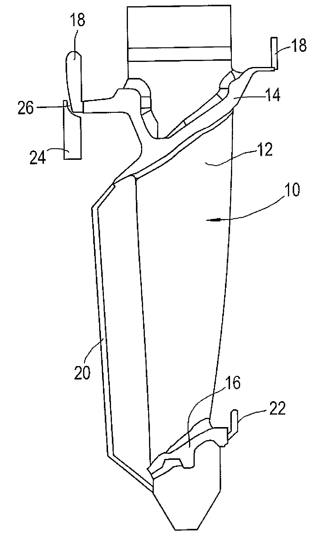
[0017]FIG. 1 shows part of a wax structure 10 usable in casting a turbine blade for a jet engine. This would typically be an integral part of a larger wax structure usable to form a mould. The features which will form the blade can be seen in the structure 10, being namely an aerofoil 12 extending between upper and lower platforms 14, 16. Extending upwardly from the part forming the upper platform 14 are two tabs 18 which in a mould form feeders to supply molten metal to difficult to cast areas.

[0018]A link 20 of wax extends between the upper platform 14 and lower platform 16 providing in a mould a continuation bar to ensure consistent grain growth to the lower platform part 16. A further tab 22 is provided on the opposite side of the lower platform part 16 to the link 20, to provide a feed of molten metal to the lower platform part 16.

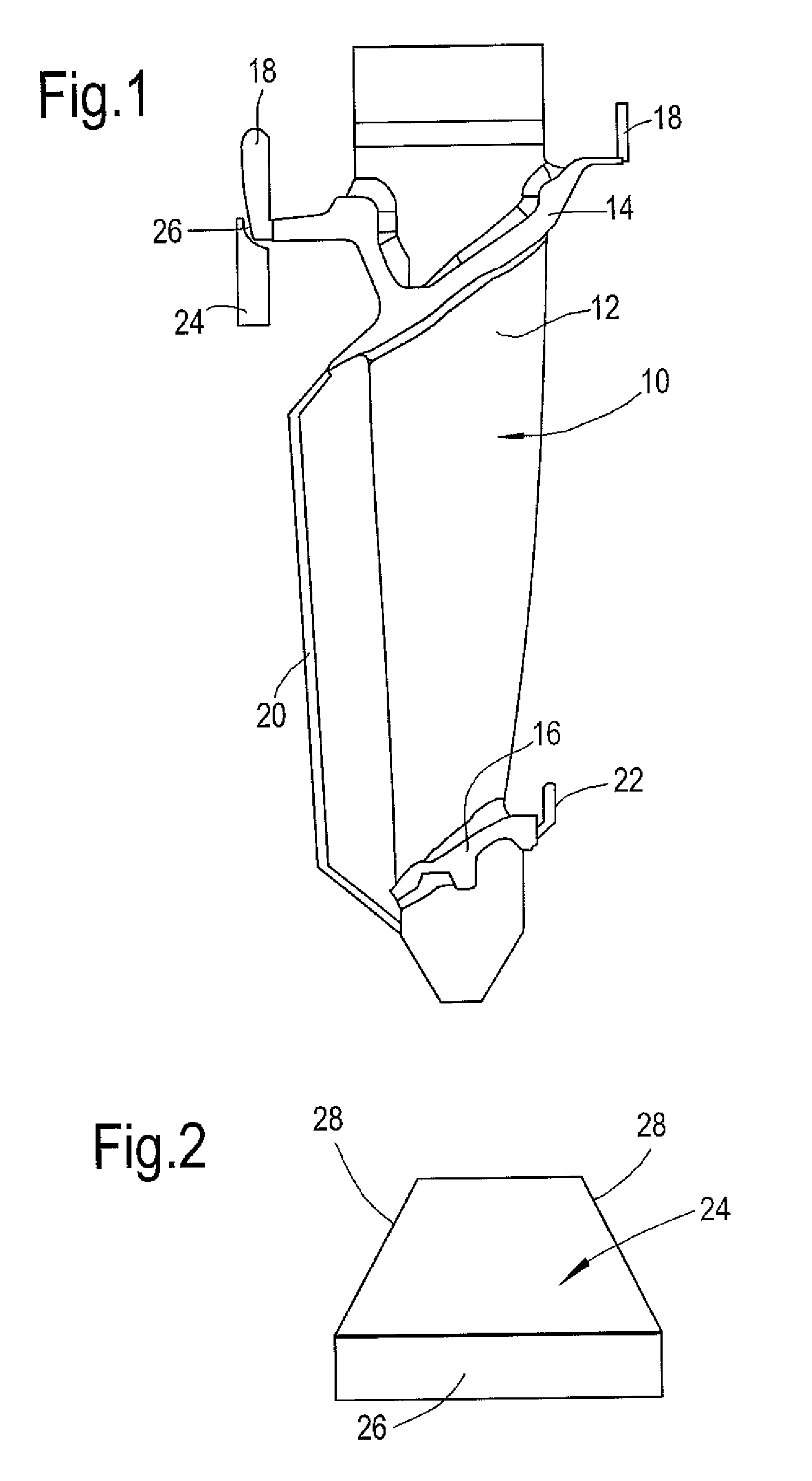
[0019]Attached to the left hand tab 18 as shown, and extending downwardly therefrom, is a ceramic piece 24 (see FIG. 2). The piece 24 has a substanti...


PUM


Abstract

In the casting of a single crystal component, such as a turbine blade, by the lost wax casting technique, one or more ceramic pieces are positioned on a wax pattern at locations corresponding to parts of the cast component where relatively quick solidification of molten metal may occur during casting. A coating is subsequently formed around the wax pattern to define a mould, whereupon the wax is removed to leave the one or more ceramic pieces within the formed mould.

Description

CROSS REFERENCE TO RELATED APPLICATION[0001]This application is entitled to the benefit of British Patent Application No. GB 0901663.5, filed on Feb. 4, 2009.FIELD OF THE INVENTION[0002]This invention concerns a method of single crystal casting of a component, and particularly but not exclusively a turbine blade for a jet engine, a method of forming a mould for use in single crystal casting, and a mould for use in single crystal casting.BACKGROUND OF THE INVENTION[0003]Component casting is used in order to produce a wide range of components and members. Essentially, the component is cast in a mould from a molten liquid and then allowed to cool in order to leave a solidified component. Some components such as turbine blades for jet engines require structural abilities such as high temperature creep resistance. This is achieved with turbine blades through forming a single crystal. At high temperatures, typically above half the absolute melting temperatures of the metal, the grain boun...

Claims


Application Information

Patent Timeline
IPC IPC(8): B22D27/04B22C9/00B22D15/00
CPCB22D27/045B22C9/043
Inventor CREASEY, PAUL ANDREW
Owner ROLLS ROYCE PLC
Why Eureka
Try Eureka