

Two-dimensional touch panel
- Summary
- Abstract
- Description
- Claims
- Application Information
AI Technical Summary
Benefits of technology
Problems solved by technology
Method used
Image

Examples
first embodiment
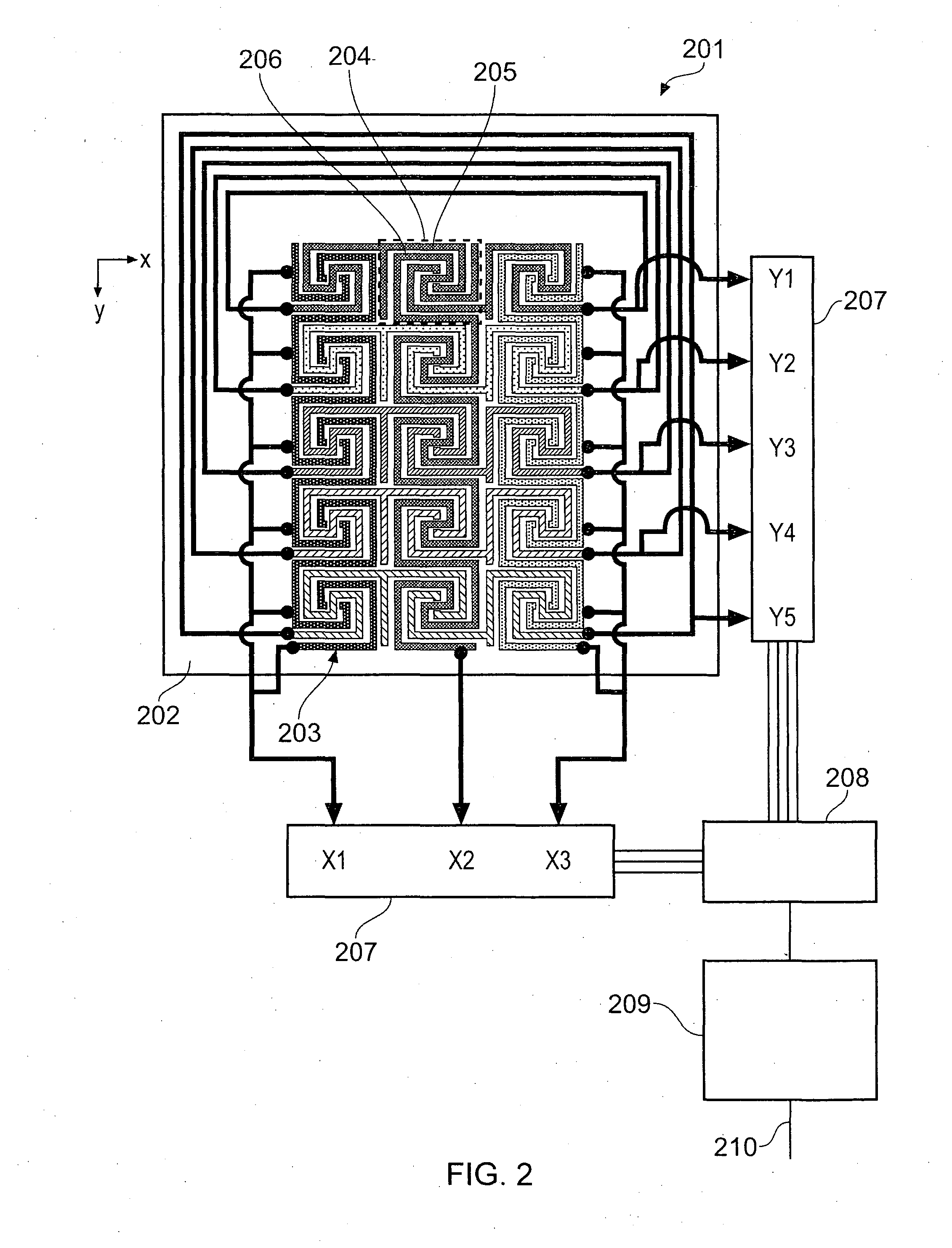
[0046]FIG. 2 schematically shows in plan view a 2D touch-sensitive capacitive position sensor 201 according to the invention. The 2D touch-sensitive capacitive position sensor will be used to describe how the algorithm shown in FIG. 3 is used to compute the position of multiple objects adjacent to the position sensor.
[0047]The 2D touch-sensitive capacitive position sensor 201 is operable to determine the position of objects along a first (x) and a second (y) direction, the orientation of which are shown towards the top left of the drawing. The sensor 201 comprises a substrate 202 having sensing electrodes 203 arranged thereon. The sensing electrodes 203 define a sensing area within which the position of an object (e.g. a finger or stylus) to the sensor may be determined. The substrate 202 is of a transparent plastic material and the electrodes are formed from a transparent film of Indium Tin Oxide (ITO) deposited on the substrate 202 using conventional techniques. Thus the sensing a...
second embodiment
[0111]FIG. 7 is a flow diagram showing steps of the signal processing method embodied in hardware, firmware or software in the host controller 615. FIGS. 8A to 8E show the 4×6 array of touch buttons in the touch panel of the second embodiment in sequence at various points in the processing for the example set of touch inputs.
[0112]FIG. 8A shows a 4×6 grid with the raw data values of the signals acquired in a single acquisition in Step S701 of FIG. 7. Each of the grid squares represents one of the discrete keys of the capacitive position sensor 601. Two simultaneous finger touches are present at the positions indicated by the dashed lines. The raw data values are stated in arbitrary units. There is one finger touch near the top left of the panel and another finger touch near the bottom right of the panel.
[0113]FIG. 8B shows as shaded panels the positions of the five keys that have returned signals above the threshold, i.e. the in-detect keys. Each of the discrete keys is denoted by K...
PUM
 Abstract
Description
Claims
Application Information