Electrospinning of PTFE with high viscosity materials

a technology of electrospinning and high viscosity materials, applied in the direction of synthetic resin layered products, filament/thread forming, textiles and paper, etc., can solve the problems of poor fiber formation, orifice clogging, inadequate fiberization,

Active Publication Date: 2010-08-05
ZEUS COMPANY INC
View PDF25 Cites 78 Cited by
  • Summary
  • Abstract
  • Description
  • Claims
  • Application Information

AI Technical Summary

Benefits of technology

[0010]Yet another advantage is provided in a process for forming a PTFE mat. The process includes providing a dispersion comprising PTFE with a particle size of at least 0.1 microns to no more than 0.8 microns; 1 wt % to no more than 10 wt % of polyethylene oxide with a molecular weight of at least 50,000 to no more than 4,000,000; and a solvent wherein said dispersion has a viscosity of at least 50,000 cP. An apparatus is provided comprising an orifice and a target a distance from the orifice. A voltage source is provided to create a first charge at the orifice and an opposing charge at the target. The dispersion is forced through the orifice wherein the dispersion is electrostatically charged by contact with the orifice. Electrostatically charged dispersion is collected on the target to form a mat precursor which is heated to remove the solvent and the fiberizing polymer thereby forming the PTFE mat.

Problems solved by technology

If the combination of viscosity and molecular weight were too high the fiberization was considered to be inadequate.
It has long been considered undesirable to increase the viscosity of the polymer solution over about 150 poise due to thixotropic limitations which cause orifice clogging, poor fiber formation, and the like.
Furthermore, when a charged orifice is used the polymer fibers repel during flight which has long been believed to limit the number of fibers within a given volume of spray.

Method used


Image

  • Electrospinning of PTFE with high viscosity materials
  • Electrospinning of PTFE with high viscosity materials
  • Electrospinning of PTFE with high viscosity materials

Examples


Embodiment Construction

[0013]The present invention is directed to a process for the electrostatic spinning of polytetrafluoroethylene (PTFE) into continuous fibers for the formation of non-woven sheets, membranes, tubes, and coatings with potential for multiple other applications and forms. In particular, the present invention is directed to electrospinning PTFE at a very high viscosity relative to the prior art in direct contrast to that which was previously considered feasible.

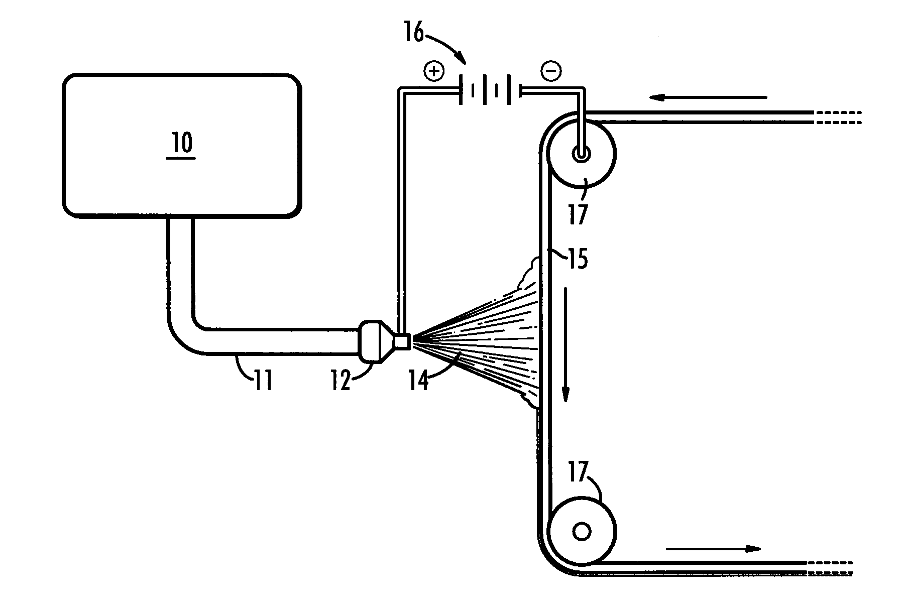
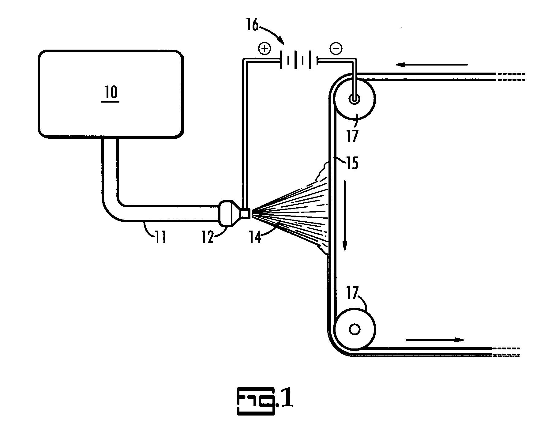
[0014]An electrostatic spinning apparatus is illustrated schematically in FIG. 1. In FIG. 1 a reservoir, 10, is loaded with a high viscosity dispersion as further described herein. A delivery system, 11, delivers the dispersion from the reservoir to a charge source, 12, which may be an orifice. A target, 15, is set some distance from the charge source, 12. A power source, 16, such as a DC power supply establishes an electrical charge differential between the charge source and target such that polymeric material, 14, is electricall...


PUM

PropertyMeasurementUnit
viscosityaaaaaaaaaa
wt %aaaaaaaaaa
wt %aaaaaaaaaa

Abstract

An improved process for forming a PTFE mat is described. The process includes providing a dispersion with PTFE, a fiberizing polymer and a solvent wherein said dispersion has a viscosity of at least 50,000 cP. An apparatus is provided which comprises a charge source and a target a distance from the charge source. A voltage source is provided which creates a first charge at the charge source and an opposing charge at the target. The dispersion is electrostatically charged by contact with the charge source. The electrostatically charged dispersion is collected on the target to form a mat precursor which is heated to remove the solvent and the fiberizing polymer thereby forming the PTFE mat.

Description

CROSS-REFERENCE TO RELATED APPLICATIONS[0001]The present application claims priority to pending U.S. Provisional Patent Appl. No. 61 / 145,309 filed Jan. 16, 2009 and to pending U.S. Provisional Patent Appl. No. 61 / 256,349 filed Oct. 30, 2009 both of which are incorporated by reference.BACKGROUND OF THE INVENTION[0002]The present invention is specific to a process of electrospinning polytetrafluoroethylene (PTFE). More particularly, the present invention is related to electrospinning high viscosity PTFE dispersions and products manufactured thereby.[0003]The process of electrostatic spinning is well known in the art as represented in U.S. Pat. Nos. 2,158,416; 4,043,331; 4,143,196; 4,287,139; 4,432,916; 4,689,186; 6,641,773 and 6,743,273 each of which is incorporated herein by reference thereto. U.S. Pat. Nos. 4,323,525, 4,127,706 and 4,044,404, all of which are incorporated herein by reference, provide information related to processing and electrostatic spinning of PTFE from an aqueou...

Claims


Application Information

Patent Timeline
Patent Type & Authority Applications(United States)
IPC IPC(8): B29C67/08
CPCD01D5/0038Y10T428/1314D01F6/12D01F6/48D04H1/42D04H1/4326D04H1/728D04H3/02B05D1/007B32B1/08B32B5/022B32B9/005B32B15/085B32B27/08D01D5/0007D04H1/4318D10B2321/042Y10T428/1355Y10T428/1362D01D10/02D01D5/003D04H1/413Y10T442/60Y10T442/656Y10T442/674Y10T442/681B29B11/06B29B13/023B29C55/04B29K2027/18B29K2105/0094B29K2995/0063B29K2995/0077B29L2031/755C08F114/26C08J3/005C08J3/05C08J9/232C08J2327/18C08J2471/02D04H1/54D04H1/74D06N7/00
Inventor ANNEAUX, BRUCE L.BALLARD, ROBERTGARNER, DAVID P.
Owner ZEUS COMPANY INC
Why Eureka
Try Eureka