Router device

a router and battery technology, applied in the direction of electrochemical generators, instruments, transportation and packaging, etc., can solve the problems of secondary battery degraded performance or failure, and achieve the effect of avoiding secondary battery degraded performance, avoiding impaired functionality, and enhancing service li

Inactive Publication Date: 2010-08-05
BUFFALO CORP LTD
View PDF9 Cites 4 Cited by
  • Summary
  • Abstract
  • Description
  • Claims
  • Application Information

AI Technical Summary

Benefits of technology

[0014]With the router device of the above design, because the power control portion subsequently interrupts supply of power to the router device if temperature in the vicinity of the secondary battery reaches a high temperature not smaller than a first threshold value, impaired functionality such as degraded performance or malfunction caused by excessively high temperature of the secondary battery can be avoided.
[0015]In another possible arrangement, the router device further includes an alert portion adapted to alert the user of the router device when the detected temperature is not smaller than a second threshold value, prior to interruption of supply of power by the power control portion. With the router device of this design, prior to interruption of supply of power the user will be alerted that the temperature in the vicinity of the secondary battery is not smaller than a second threshold value, so the user can opt to manually turn off the power to the router device and avoid impaired functionality of the secondary battery. Moreover, because the supply of power to the router device is not interrupted without warning, the user will be able to power down the router device at safe timing unlikely to cause any problems in the router device, after having first completed desired operation of the router device.
[0016]Here, as one process for providing the aforementioned alert, the alert portion may emit light from a light-emitting device furnished to the alert portion. Because the router device of this design issues alerts through light emission by a light-emitting device, the user can readily ascertain if the temperature in the vicinity of the secondary batter...

Problems solved by technology

However, if such a router device powered by secondary battery is used in a high temperature environment, or if the temperature in proximity to the secondary battery should become elevated due for example to latch-up of a component situated in proximity to the second...

Method used


Image

  • Router device
  • Router device
  • Router device

Examples


embodiment

A. Embodiment

[0024]The embodiment of the present invention will be discussed below.

[0025]A-1. Device Configuration:

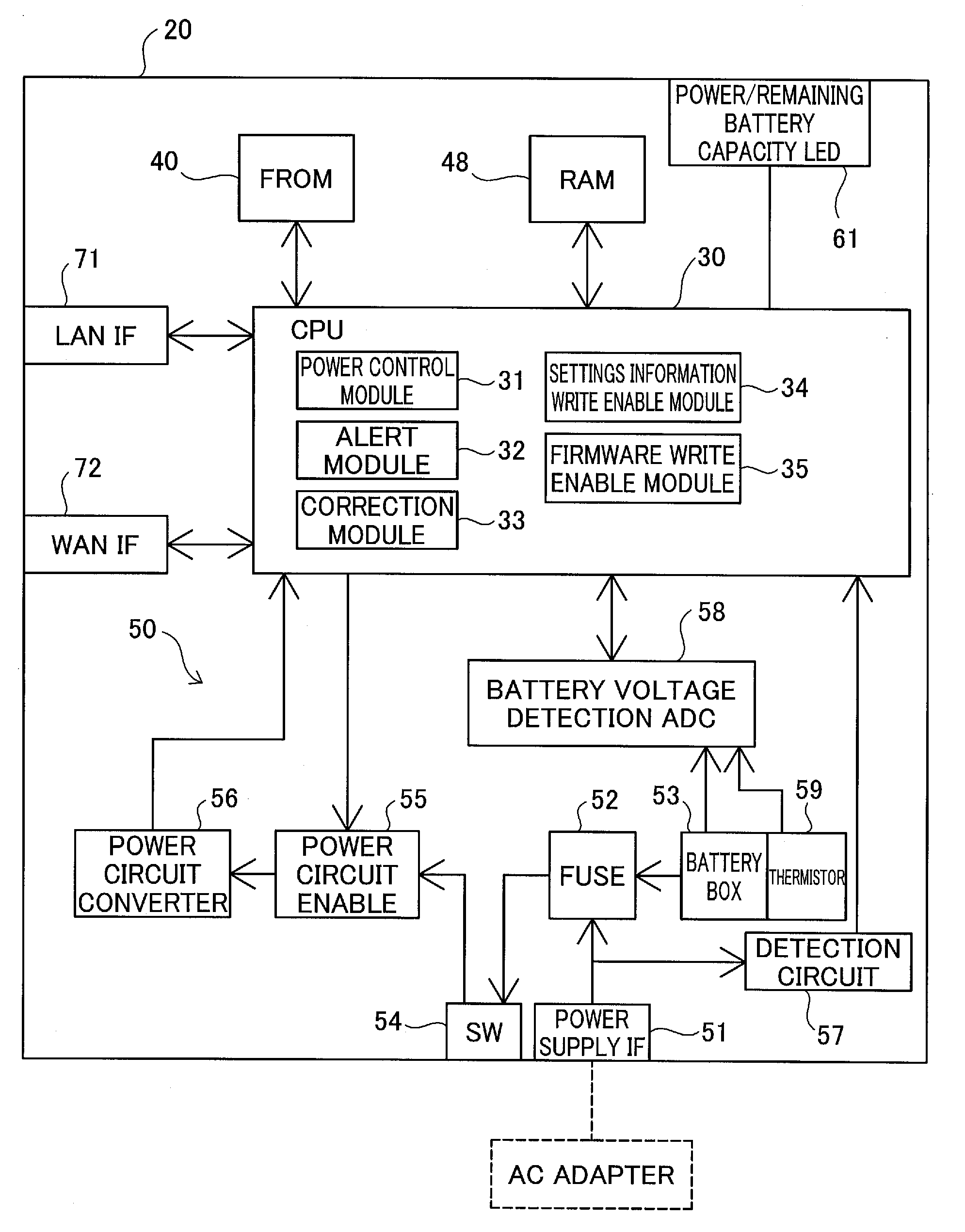
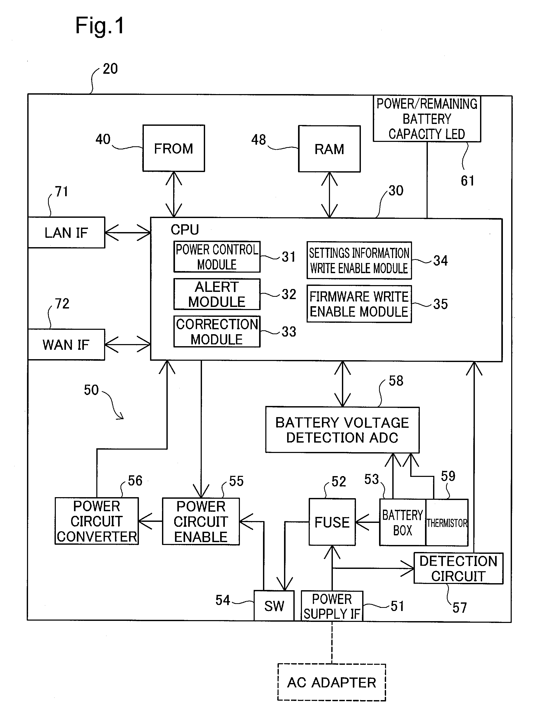
[0026]FIG. 1 depicts a simplified configuration of a router device 20 presented as an embodiment of the present invention. The router device 20 is one adapted to forward communication packets from a first network to a second different network. The router device 20 is furnished with a CPU 30, a flash ROM 40, RAM 48, a power control circuit 50, a Power / Remaining Battery Capacity LED 61, a LAN interface 71, and a WAN interface 72, these components being respectively connected by an internal bus.

[0027]The CPU 30 controls overall operation of the router device 20 by loading firmware or a program stored in the flash ROM 40 (a rewriteable nonvolatile storage medium) into the RAM 48 and executing the code. The CPU 30 also functions as a power control module 31, an alert module 32, a correction module 33, a settings information write enable module 34, and a firmware write enable...

modification 1

B-1: Modification 1

[0072]The embodiment set forth above employs an arrangement whereby, in Step S120 of the first operation restriction process, the router device 20 alerts of high temperature in the vicinity of the secondary battery by flashing the Power / Remaining Battery Capacity LED 61; however, no particular limitation is imposed as to the alert method. For example, the router device 20 could be furnished with an LED exclusively for alert use, and issue alerts by some other light emission process, such as illuminating this LED.

[0073]Nor is the alert method limited to one of light emission by a light-emitting device, and an audio alert arrangement would be acceptable as well. Alternatively an arrangement whereby the router device 20 sends an e-mail alert to a preregistered e-mail address of the user would be acceptable.

[0074]As another alternative, an arrangement whereby, using JavaScript™ or the like, an alert window pop-up display is produced on the display screen of an informa...

modification 2

B-2: Modification 2

[0075]In the embodiment above, the router device 20 has been designed to execute the first operation restriction process regardless of whether secondary battery have been installed in the battery box 53. By so doing, even if secondary battery have not been installed in the battery box 53, it will be possible to avoid situations in which a component of the router device 20 reaches excessively high temperature due to latch-up or the like, resulting in problems such as malfunction or failure. However, an arrangement whereby the first operation restriction process is executed only if secondary battery are installed in the battery box 53 would also be acceptable. Such an arrangement could be accomplished, for example, by having the CPU 30 determine secondary battery installation status based on output from the battery voltage detection ADC 58; or by providing in the interior of the battery box 53 a switch that is designed to depress when secondary battery are installed...


PUM


Abstract

The router device acquires detected temperature T from a thermistor provided inside the battery box containing secondary battery that provide the power supply, and if the detected temperature T is not smaller than a threshold value Th1, produces flashing display of an LED to alert the user. If the detected temperature T is not smaller than a threshold value Th2 additionally, supply of power to the CPU of the router device is subsequently interrupted. In this way, in a router device powered by a secondary battery, diminished functionality of the secondary battery due to elevated temperature may be prevented.

Description

CROSS-REFERENCE TO RELATED APPLICATION[0001]The present application claims priority from Japanese application P2009-20291A filed on Jan. 30, 2009, the content of which is hereby incorporated by reference into this application.BACKGROUND[0002]1. Field of the Invention[0003]The present invention relates to a router device adapted to forward communication packets over a network.[0004]2. Description of the Related Art[0005]Recent advances in networking technology have led to widespread adoption of mobile computing. In the field of router devices as well, compact products that are ultraportable have been developed. Devices designed to utilize secondary battery or the like as the power supply can be contemplated as one type of such router device.[0006]However, if such a router device powered by secondary battery is used in a high temperature environment, or if the temperature in proximity to the secondary battery should become elevated due for example to latch-up of a component situated i...

Claims


Application Information

Patent Timeline
IPC IPC(8): H02J7/00G06F3/048
CPCH01M10/486H01M10/443Y02E60/10
Inventor HIBI, AKIHITOTAMURA, YOSHITERU
Owner BUFFALO CORP LTD
Why Eureka
Try Eureka