Clamping Device And Object Loading Method

a technology of object and clamping force, which is applied in the direction of machine supports, printing, printing, etc., can solve the problems of reducing the overlay performance of the projection of the lithographic apparatus, affecting the final product quality, and affecting the quality of the final product, so as to reduce the risk of stress in the substrate and/or overlay errors, and reduce the internal stress in the substrate due to clamping force.

Active Publication Date: 2010-08-05
ASML NETHERLANDS BV
View PDF36 Cites 20 Cited by
  • Summary
  • Abstract
  • Description
  • Claims
  • Application Information

AI Technical Summary

Benefits of technology

[0009]Applicants have determined that it is be desirable to provide a substrate support having a holding arrangement for substrates, wherein internal stresses in a substrate due to clamping forces are substantially decrea

Problems solved by technology

As a result, stresses may be induced in the substrate when it is clamped on the supporting surface.
These stresses may have a negative influence on the final product quality.
Also, since the s

Method used


Image

  • Clamping Device And Object Loading Method
  • Clamping Device And Object Loading Method
  • Clamping Device And Object Loading Method

Examples


Embodiment Construction

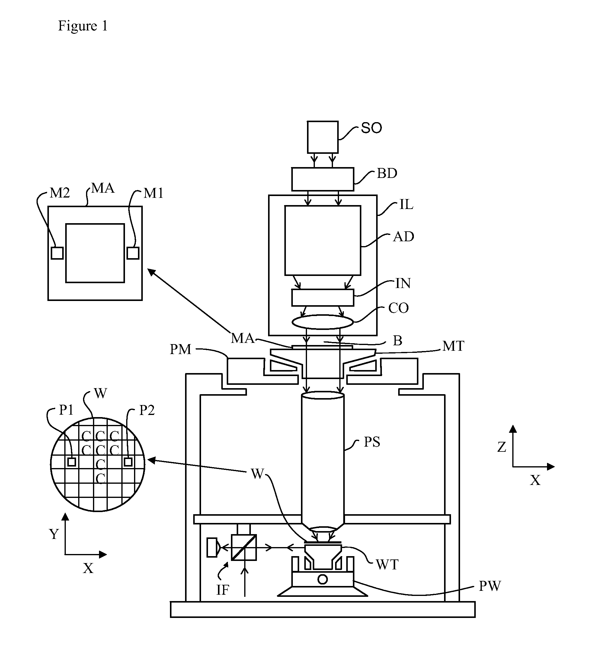
[0025]FIG. 1 schematically depicts a lithographic apparatus according to one embodiment of the invention. The apparatus includes an illumination system (illuminator) IL configured to condition a radiation beam B (e.g., UV radiation or any other suitable radiation), a mask support structure (e.g., a mask table) MT constructed to support a patterning device (e.g., a mask) MA and connected to a first positioning device PM configured to accurately position the patterning device in accordance with certain parameters. The apparatus also includes a substrate table (e.g., a wafer table) WT or “substrate support” constructed to hold a substrate (e.g., a resist-coated wafer) W and connected to a second positioning device PW configured to accurately position the substrate in accordance with certain parameters. The apparatus further includes a projection system (e.g., a refractive projection lens system) PS configured to project a pattern imparted to the radiation beam B by patterning device MA...


PUM


Abstract

The present invention relates to a c lamping device configured to clamp an object (20, 120) on a support (1, 101). The clamping device comprises: a first device configured to force the object and the support away from each other using a first force, and a second device configured to force the object and the support towards each other using a second force. The first device and second device are configured to simultaneously exert the first force and the second force respectively to shape the object to a desired shape before completing the clamping of the object on the support.

Description

BACKGROUND[0001]1. Field of the Invention[0002]The present invention relates to a clamping device and a method for clamping an object on a support. The present invention further relates to a lithographic apparatus and a method for loading a substrate on a substrate support of a lithographic apparatus. Finally, the present invention relates to a machine readable medium.[0003]2. Description of the Related Art[0004]A lithographic apparatus is a machine that applies a desired pattern onto a substrate, usually onto a target portion of the substrate. A lithographic apparatus can be used, for example, in the manufacture of integrated circuits (ICs). In such a case, a patterning device, which is alternatively referred to as a mask or a reticle, may be used to generate a circuit pattern to be formed on an individual layer of the IC. This pattern can be transferred onto a target portion (e.g., including part of, on1e, or several dies) on a substrate (e.g., a silicon wafer). Transfer of the pa...

Claims


Application Information

Patent Timeline
IPC IPC(8): G03B27/58F16M13/00G06F19/00B25B5/00
CPCG03F7/707G03F7/70783H01L21/6875H01L21/68742H01L21/6838
Inventor COMPEN, RENE THEODORUSJACOBS, JAHANNES HENRICUS WILHELMUSLEENDERS, MARTINUS HENDRIKUS ANTONIUSOTTENS, JOOST JEROENSMEETS, MARTIN FRANS PIERRE
Owner ASML NETHERLANDS BV
Why Eureka
Try Eureka