
Efficient optical arrangement for illumination and detection of Label-Free biosensors and method to reduce interference fringes in label-free imaging

Inactive Publication Date: 2010-08-05
X BODY
View PDF9 Cites 22 Cited by
  • Summary
  • Abstract
  • Description
  • Claims
  • Application Information

AI Technical Summary

Benefits of technology

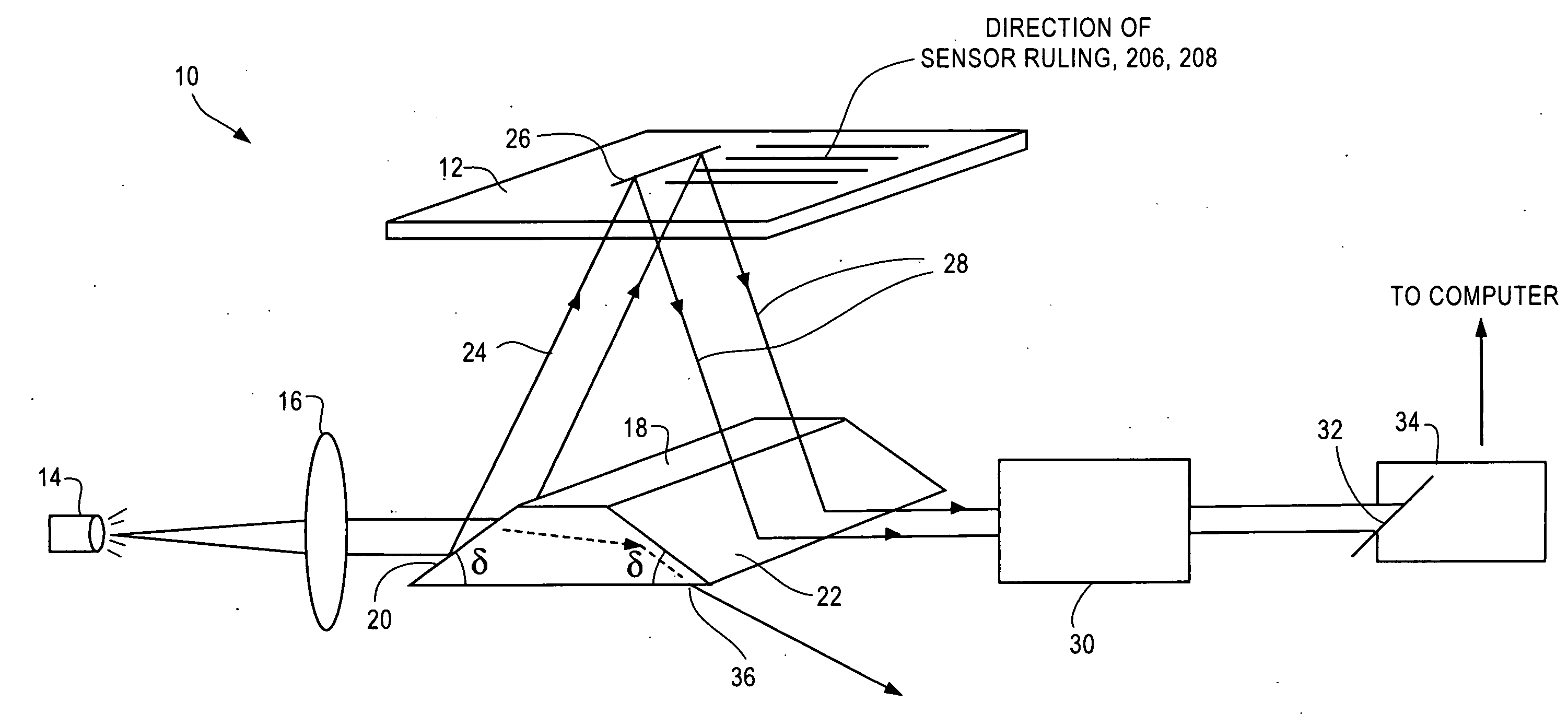
[0009]Additionally, preferred embodiments are describe below wherein the incident light impinges upon the biosensor surface at a non-normal angle of incidence, such as between about 6 and 12 degrees. The deviation from normal incidence is chosen to be parallel to the direction of the grating lines on the sensor. It has been discovered that with non-laser (incoherent) light sources in this arrangement (such as LED or arc lamp sources), undesirable interference fringes in the spectrum essentially disappear and thereby allows more precise measurements of the peak wavelength of reflected (or transmitted) light from the sensor to be obtained. In this regard, a method for reducing interference fringes produced in label-free imaging of a photonic crystal biosensor having a periodic grating structure in the form of lines having a direction is described, comprising the steps of: providing a light source generating incoherent light; directing the incoherent light through collimating optics and generating collimated the light from the light source; directing the collimated light onto a surface of the biosensor at a non-normal angle of incidence, and wherein the deviation from normal incidence is chosen to be parallel to the said direction of the lines of the periodic grating structure; directing light reflected from the biosensor to telecentric optics and directing light from the telecentric optics to a spectrometer.

Problems solved by technology

Biochemical interactions occurring on the surface of the biosensor cause a change in the index of refraction of the biosensor surface, which results in a small shift in the PWV.

Method used


Image

  • Efficient optical arrangement for illumination and detection of Label-Free biosensors and method to reduce interference fringes in label-free imaging
  • Efficient optical arrangement for illumination and detection of Label-Free biosensors and method to reduce interference fringes in label-free imaging
  • Efficient optical arrangement for illumination and detection of Label-Free biosensors and method to reduce interference fringes in label-free imaging

Examples


Embodiment Construction

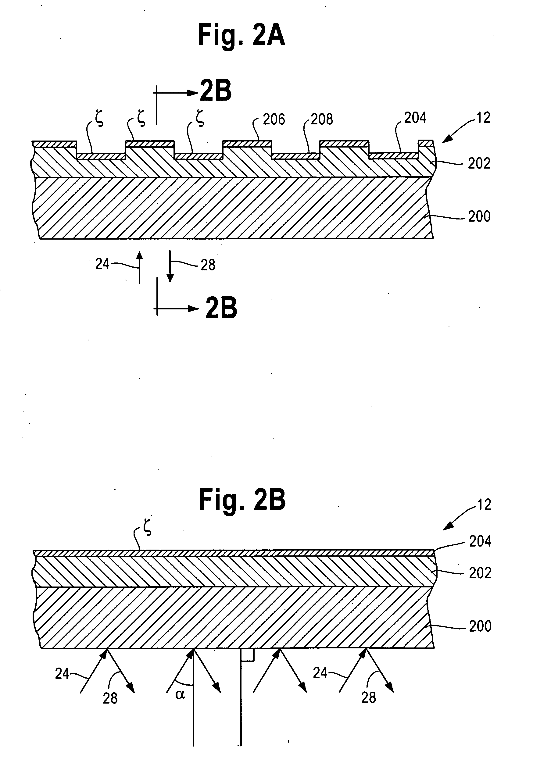
[0016]The optical arrangement for illuminating a biosensor in accordance with a first embodiment of this disclosure uses a non-right angle prism to illuminate the sensor and receive its reflected signal at an equal angle slightly off axis. A presently preferred arrangement 10 is shown in FIG. 1. The arrangement is used for illuminating a surface of a biosensor 12 having a periodic surface grating structure, which is shown in more detail in FIG. 2A. The biosensor 12 may take the form of a photonic crystal biosensor of the type described in the above-referenced patent literature. Other types of biosensors can be used as wells, such as those described in Wawro, U.S. Pat. No. 7,400,399, Duveneck et al., U.S. Pat. No. 6,395,558; Published PCT application. WO 98 / 09156; PCT / EP94 / 02361; and Budach et al., U.S. Pat. No. 6,707,561.

[0017]The arrangement 10 includes a light source 14 generating light. The light source 14 is preferably a quasi-point source, such as a Light Emitting Diode (LED). ...


PUM


Abstract

An optical arrangement for illuminating a surface of a biosensor is described. The biosensor is preferably a sensor having periodic surface grating structure. The arrangement includes a light source generating light, collimating optics for collimating the light from the light source, and first reflecting surface receiving light from the collimating optics and directing incident light onto a surface of the biosensor and a second spatially separated reflecting surface receiving light reflected from the surface of the biosensor. The arrangement further includes telecentric optics (e.g., telecentric lens) receiving light from the second surface of the prism. The telecentric lens directs light onto an entrance slit of a spectrometer. The arrangement increases the light collection efficiency at the spectrometer as compared to prior art to prior art arrangements. The use of an incoherent light source and an arrangement in which incident light impinges upon the biosensor surface at a non-normal angle of incidence parallel to the direction of the grating lines on the sensor eliminates undesirable interference fringes in peak wavelength value measurements of the sensor.

Description

PRIORITY[0001]This application claims priority benefits under 35 U.S.C. §119(e) to U.S. Provisional Application Ser. No. 61 / 206,676 filed Feb. 2, 2009.BACKGROUND [0002]This invention relates to optical arrangements for illumination of the surface of a optical biosensor and the detection of interactions, typically biochemical interactions, occurring on the surface of the biosensor.[0003]The applicant's assignee SRU Biosystems, Inc. of Woburn Mass. has developed and commercialized a label-free photonic crystal optical biosensor in which the surface of the biosensor includes a periodic surface grating. The biosensors are described in the patent literature, see for example U.S. patent application publications U.S. 2003 / 0027327; 2002 / 0127565, 2003 / 0059855 and 2003 / 0032039, the content of which is incorporated by reference herein.[0004]SRU Biosystems has also developed a reading instrument for the biosensors. The reading instrument includes a light source (which can take the form of a whi...

Claims


Application Information

Patent Timeline
IPC IPC(8): G01J3/28
CPCG01N21/4788G01N21/7743G01N21/75G01N21/8806
Inventor ROCKNEY, BENNETT H.
Owner X BODY
Learn More