Optical information recording medium and recording and reproduction apparatus

a technology of optical information and recording medium, applied in mechanical recording, recording information storage, instruments, etc., can solve the problems of recording and reproduction not being able to perform, the position of the beam spot is greatly affected, and the distortion of the concentrated beam, so as to reduce the influence of interlayer crosstalk, reduce the process margin, and eliminate the effect of back-focus issues

Inactive Publication Date: 2010-08-05
PANASONIC CORP
View PDF15 Cites 25 Cited by
  • Summary
  • Abstract
  • Description
  • Claims
  • Application Information

AI Technical Summary

Benefits of technology

[0039]According to the present invention, a sufficient process margin for manufacturing intermediate layers and protective layers is secured for a multilayer optical information recording medium including three or more information layers. Furthermore, according to the present invention, it is possible, in a multilayer optical information recording medium, to ensure compatibility with conventional single- and dual-layer optical information recording media, reduce the influence of interlayer crosstalk, and furthermore eliminate back-focus issues.

Problems solved by technology

However, when the spot is small, the position of the beam spot is greatly affected by disk tilt.
In other words, aberration will occur in the beam spot with even a slight tilt in the disk, causing distortion in the concentrated beam; this results in a problem in that recording and reproduction cannot be performed.
When stray light is reflected in multiple through one of the information layers and returns to the optical head along the same optical path as the information light, the stray light interferes with the information light, causing large fluctuations in the light amount.
Problems caused by such interference are particularly apparent in multilayer media having three or more information layers.
Such fluctuation in the light amounts caused by interference between the information light to be read out and stray light is called a “back-focus issue”.

Method used


Image

  • Optical information recording medium and recording and reproduction apparatus
  • Optical information recording medium and recording and reproduction apparatus
  • Optical information recording medium and recording and reproduction apparatus

Examples


Embodiment Construction

[0074]Embodiments of the present invention shall now be described with reference to the drawings.

1. Outline of Structure of Three-Layer Disk

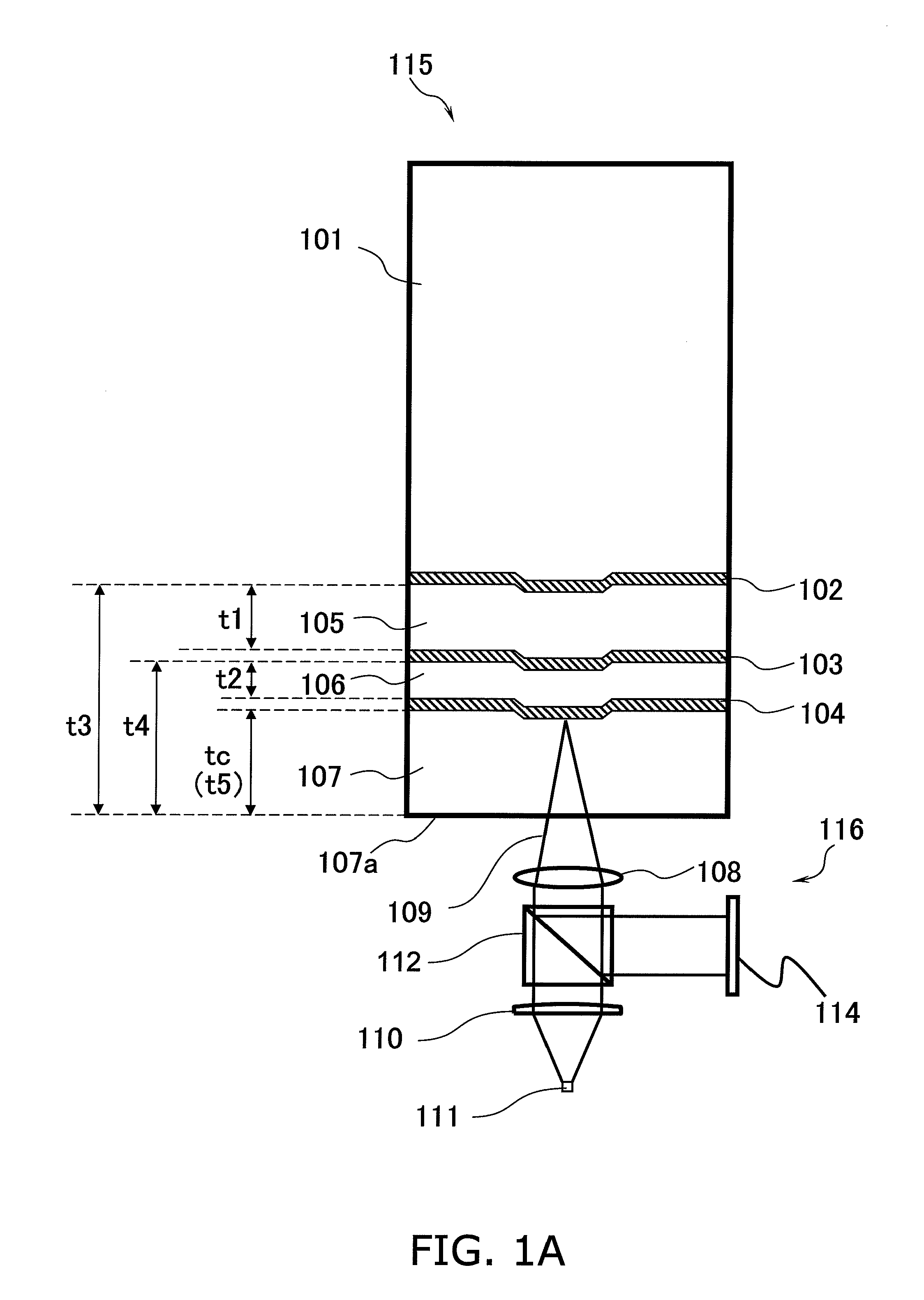
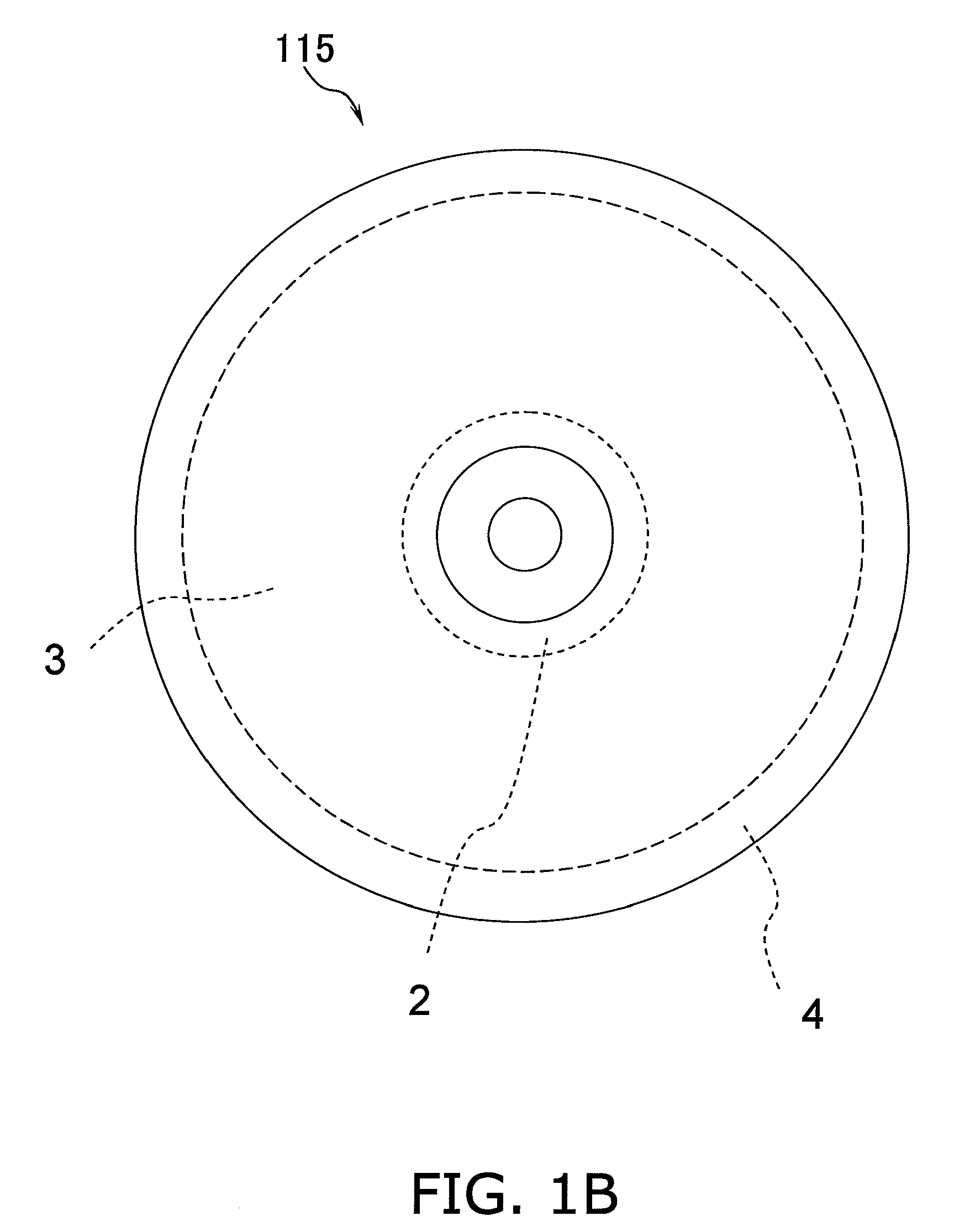
[0075]FIG. 1A is a cross-section of a disk 115 (an optical information recording medium; a three-layer disk) according to a first embodiment of the present invention, and also schematically illustrates a part of an apparatus that records information onto the disk 115 and / or reads out information from the disk 115.

[0076]Note that in the present specification, the term “optical information recording medium” includes various recording media such as DVDs, CDs, Blu-ray disks, and so on. A “disk” is a disk-shaped recording medium. With the exception of the descriptions of the related art, the “optical information recording medium” referred to in the present specification is also sometimes called simply a “recording medium”, a “medium”, an “optical disk”, a “disk”, or the like. In other words, in the following description, these terms are often used in...


PUM

PropertyMeasurementUnit
thicknessesaaaaaaaaaa
thicknessaaaaaaaaaa

Abstract

A disk-shaped optical information recording medium (115) includes a substrate (101), first to nth information layers (102-104) layered upon the substrate (where n is an integer of 3 or more), kth intermediate layers (105, 106) provided between a kth information layer and a (k+1)th information layer (where k=1, 2, and so on up to n−1), and a protective layer (107) provided upon the nth information layer. The fluctuation range of the thicknesses from the protective layer surface (107a) to each of the information layers (102-104) is no more than ±3 μm relative to the average value of the thicknesses within a range from a radius of 23 mm to 24 mm from the center of the optical information recording medium.

Description

TECHNICAL FIELD[0001]The present invention relates to an optical information recording medium having a thin film formed upon a substrate and that is capable of recording information such as audio / video as a digital signal that can be reproduced. The recording of information onto the optical information recording medium can be executed using a high-energy light beam such as a laser beam. The present invention particularly relates to an optical information recording medium capable of recording a large amount of information through the multilayering of information layers.BACKGROUND ART[0002]Research into optical information recording techniques has been advancing in recent years. The optical information recording media being developed are widely used for industrial and consumer uses. In particular, optical information recording media capable of recording information at high densities, such as CDs and DVDs, have become widespread. Such optical information recording media have a transpar...

Claims


Application Information

Patent Timeline
Patent Type & Authority Applications(United States)
IPC IPC(8): G11B7/26G11B7/135G11B7/24G11B7/24035G11B7/24038G11B7/24047
CPCG11B7/0948G11B2007/0013G11B7/24038G11B7/13927
Inventor TSUKUDA, MASAHIKOTOMIYAMA, MORIO
Owner PANASONIC CORP
Why Eureka
Try Eureka