
Optical communication system and arrangement converter

a technology of optical communication system and arrangement converter, which is applied in the field of optical communication system, can solve the problems of difficult optically linking such an optical device to a multicore fiber, difficult to increase the number of cores per multicore fiber of the multicore fiber described in document 2, and the increase in the number of cores is clearly limited

Active Publication Date: 2010-08-05
SUMITOMO ELECTRIC IND LTD
View PDF22 Cites 37 Cited by
  • Summary
  • Abstract
  • Description
  • Claims
  • Application Information

AI Technical Summary

Benefits of technology

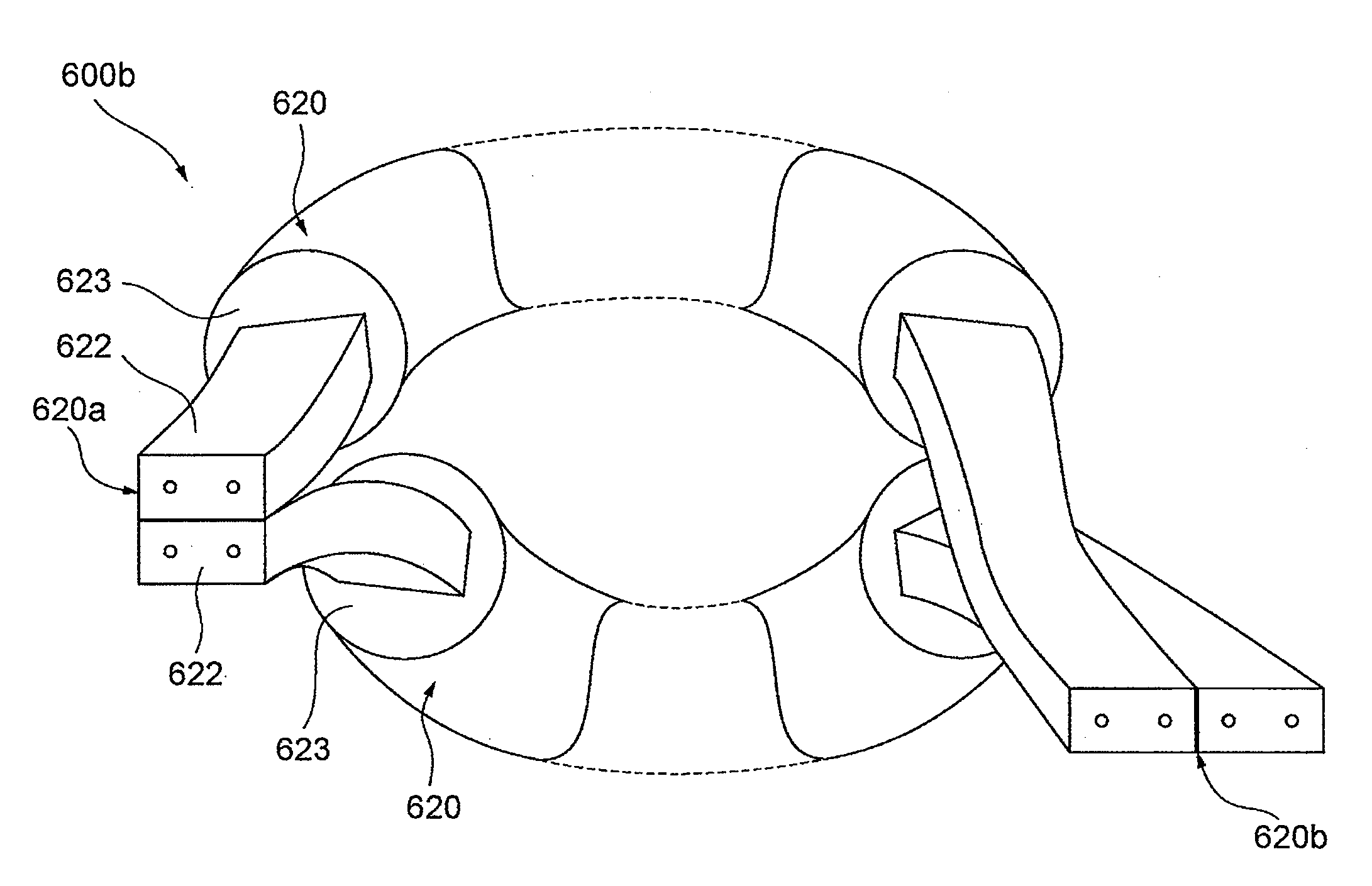
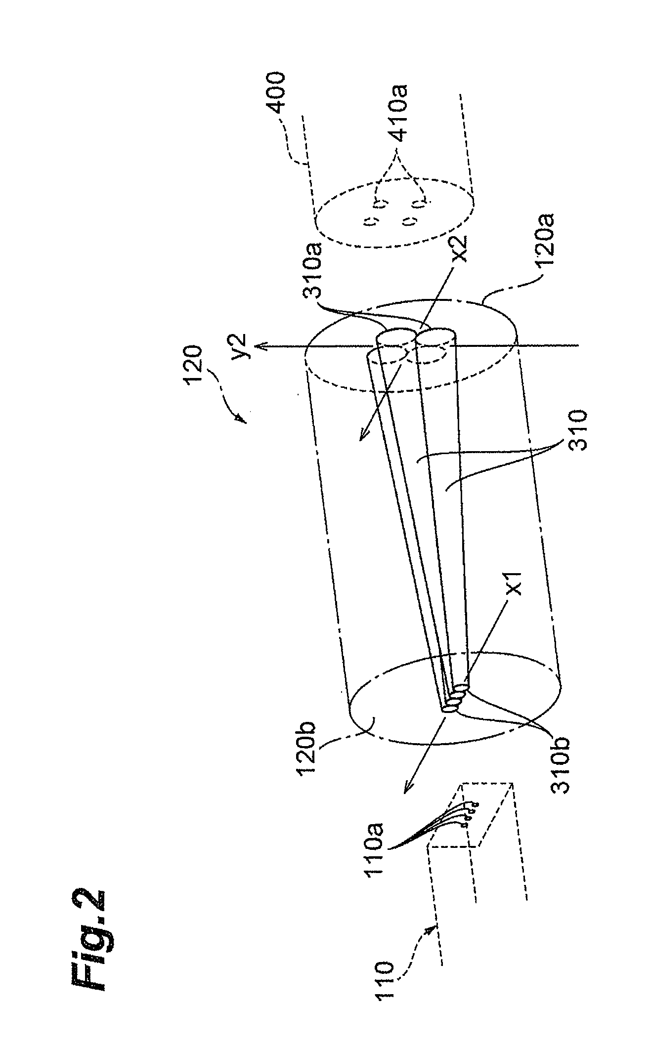
[0013]The present invention has been developed to eliminate the problems described above. It is an object of the present invention to provide an optical communication system which adopts a multicore fiber that includes, as part of an optical fiber network, a plurality of two-dimensionally arrayed cores, as well as an arrangement converter which serves as a connector to enable a favorable optical link between a variety of constituent elements (network resources) in the optical communication system, and which has a structure that enables an optical link between network resources in which the arrays of light entry units and light exit units differ, and which alleviates the conventional limitations governing the number of optical waveguides.

Problems solved by technology

As is also described in Document 2, an optical device such as a normally manufactured optical waveguide or semiconductor optical integrated device typically has a plurality of optical transmission / reception elements (light emitting areas or light receiving areas) arrayed one-dimensionally, and it has proven difficult to optically link such an optical device to a multicore fiber which has a plurality of cores arrayed two-dimensionally in the cross-section thereof.
Furthermore, it is hard for the multicore fiber described in Document 2 to increase significantly the number of cores per multicore fiber.
Therefore, as comparing such a case with a case where a plurality of cores are arranged two-dimensionally in a cross-section of the multicore fiber, any increase in the number of cores is clearly limited.
Note that, as a method of arraying a plurality of cores in a straight line, reducing the core spacing may be considered; however, in view of crosstalk between adjacent cores, the minimum value for the core spacing that can be applied to an optical communication system is limited according to the length and communication quality of the fiber.

Method used


Image

  • Optical communication system and arrangement converter
  • Optical communication system and arrangement converter
  • Optical communication system and arrangement converter

Examples


first embodiment

of the Optical Communication System

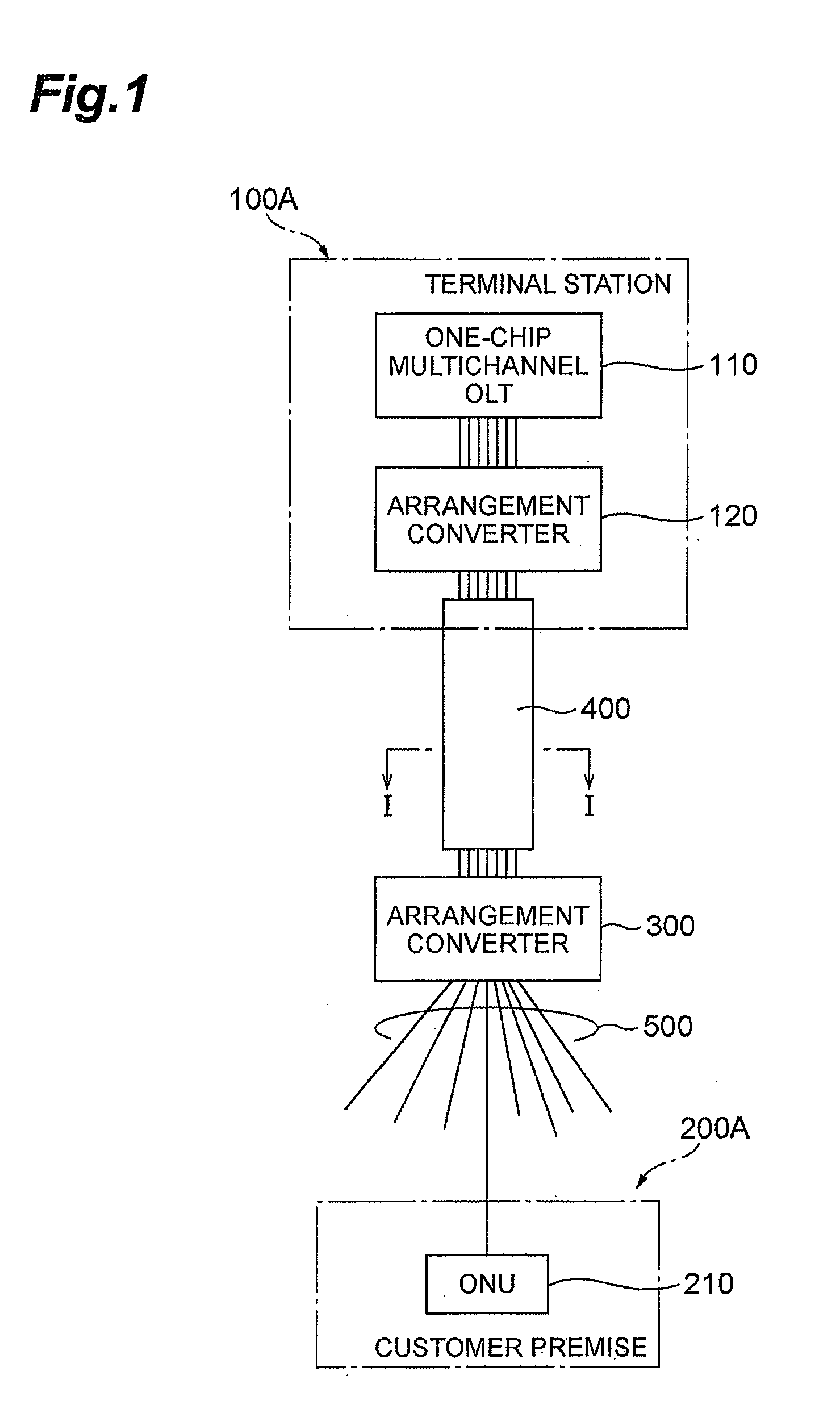
[0044]FIG. 1 is a view showing a configuration of a first embodiment of an optical communication system according to the present invention. The optical communication system according to the first embodiment provides, as per FIG. 17, FTTH (Fiber To The Home) services that enable optical communications between a single transmitter station and a plurality of customers. Note that the optical communication system shown in FIG. 1 is an SS (Single Star) system that outputs a plurality of signal channels from a transmitter station via a multicore fiber.

[0045]Namely, the SS system according to the first embodiment comprises a terminal station 100A (transmitter station), which is an endpoint relay station of an existing communication system such as the Internet, a customer premises 200A (customer), and a multicore fiber 400, which constitutes part of an optical fiber network that is laid between the terminal station 100A and the customer premises 200A (custo...

second embodiment

of the Optical Communication System

[0078]FIGS. 15A and 15B are views showing a configuration of a second embodiment of an optical communication system according to the present invention. The optical communication system according to the second embodiment is also an SS (Single Star) system that outputs a plurality of signal channels from a terminal station 100B serving as a transmitter station via a multicore fiber 400 in the same manner as in the first embodiment, wherein the SS system provides FTTH (Fiber To The Home) services, which enable optical communications between the terminal station 100B and a plurality of customers 200B.

[0079]Namely, the SS system according to the second embodiment comprises, as shown in FIG. 15B, a terminal station 100B (transmitter station), which is the final relay station of an existing communication system such as the Internet, a customer premises 200B (customer), and a multicore fiber 400, which constitutes part of an optical fiber network that is l...

third embodiment

of the Optical Communication System

[0083]FIGS. 16A and 16B are views showing a configuration of a third embodiment of the optical communication system according to the present invention. The optical communication system according to the third embodiment is a many-to-many large-capacity optical communication system that is capable of transmitting and receiving a plurality of signal channels via the multicore fiber 400 and, as shown in FIG. 16B, comprises a transmitter station 100C, a receiver station 200C, and a multicore fiber 400 which constitutes part of an optical fiber network that is laid between the transmitter station 100C and the receiver station 200C (receiver station) and which includes a plurality of cores (optical waveguide regions) that are two-dimensionally arrayed on both end faces thereof. However, the optical communication system according to the third embodiment differs from that of the second embodiment in that the receiver station 200C of the former comprises a o...


PUM


Abstract

The present invention relates to an optical communication system or the like, which comprises a multicore fiber with a plurality of cores that are two-dimensionally arrayed in a cross-section thereof. In the optical communication system, an arrangement converter, provided between a multicore fiber and an Optical Line Terminal (OLT) having light emitting areas arrayed one-dimensionally, comprises first and second end faces, and a plurality of optical waveguides. The optical waveguides are disposed such that one of the end faces coincides with the first end face and the other end face coincides with the second end face. In particular, the optical waveguide end face array on the first end face and the optical waveguide end face array on the second face are different, contributing to an optical link between network resources of different types.

Description

BACKGROUND OF THE INVENTION[0001]1. Field of the Invention[0002]The present invention relates to an optical communication system that comprises, as part of an optical fiber network, a multi-core fiber having a cross-section in which a plurality of cores are two-dimensionally arrayed, and to an arrangement converter which serves as a connector that can be adopted by the optical communication system and which enables a favorable optical link between various network resources.[0003]2. Related Background of the Invention[0004]A so-called Passive Optical Network (PON) system, in which a single optical fiber is shared by customers by including a multistage optical splitter, as shown in FIG. 17, for example, has conventionally been implemented to provide FTTH (Fiber To The Home) services, which enables optical communications between a single transmitter station and a plurality of customers.[0005]Namely, the PON system shown in FIG. 17 comprises a terminal station 1 (transmitter station), w...

Claims


Application Information

Patent Timeline
IPC IPC(8): G02B6/036G02B6/04G02B6/42H01L31/10H01L33/02H01L33/08
CPCG02B6/02042G02B6/264G02B6/4472G02B6/4249G02B6/3879
Inventor SASAOKA, EISUKE
Owner SUMITOMO ELECTRIC IND LTD
Learn More