Large Effective Area Fiber With GE-Free Core

a technology of ge-free core and effective area, applied in the field of optical fibers, can solve the problems of signal degradation, non-linear optical effect of high-power systems, and high-power systems that suffer from non-linear optical effects

Active Publication Date: 2010-08-05
CORNING INC
View PDF14 Cites 62 Cited by
  • Summary
  • Abstract
  • Description
  • Claims
  • Application Information

AI Technical Summary

Problems solved by technology

High power systems often suffer from non-linear optical effects, including self-phase modulation, four-wave-mixing, cross-phase modulation, and non-linear scattering processes, all of which can cause degradation of signals in high powered systems.
In addition, other optical fiber attributes, such as attenuation, are a major contributing factor to the degradation of the signal.
Generally, an optical waveguide fiber having a large effective area (Aeff) reduces non-linear optical effects, including self-phase modulation, four-wave-mixing, cross-phase modulation, and non-linear scattering processes, all of which can cause degradation of signals in high powered systems.
On the other hand, an increase in effective area of an optical waveguide fiber typically results in an increase in macrobending induced losses which attenuate signal transmission through a fiber.
The macrobending losses become increasingly significant over long (e.g., 100 km, or more) distances (or spacing between regenerators, amplifiers, transmitters and / or receivers.
Unfortunately, the larger the effective area of a conventional optical fiber is, the higher the macrobend induced losses tend to be.

Method used


Image

  • Large Effective Area Fiber With GE-Free Core
  • Large Effective Area Fiber With GE-Free Core
  • Large Effective Area Fiber With GE-Free Core

Examples


embodiment (

Embodiment(s) of the invention

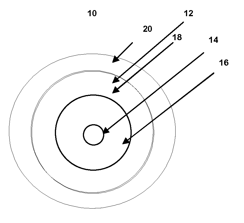
[0038]Reference will now be made in detail to the present embodiment(s) of the invention, examples of which are illustrated in the accompanying drawings. Whenever possible, the same reference numerals will be used throughout the drawings to refer to the same or like parts. One embodiment of the optical fiber of the present invention is shown in FIG. 1A, and is designated generally throughout by the reference numeral 10. The waveguide fiber 10 includes a core 12 having an effective area of at about 90 μm2 or more at a 1550 nm wavelength (for example 90 μm2 to 160 μm2, or 100 μm2 to 160 μm2, or 120 to 140 μm2 at a 1550 nm wavelength), and α value 12≦α≦200 (for example 12≦α≦100, or 12≦α≦25), and a cladding 20 surrounding the core. A typical range of a values in the exemplary fibers described herein is 14 to 20, for example 15≦α≦17. However, larger a values (e.g., >25) can be achieved by plasma chemical vapor deposition (PCVD). The exemplary refractive inde...

examples 1-15

[0048]The invention will be further clarified by the following examples.

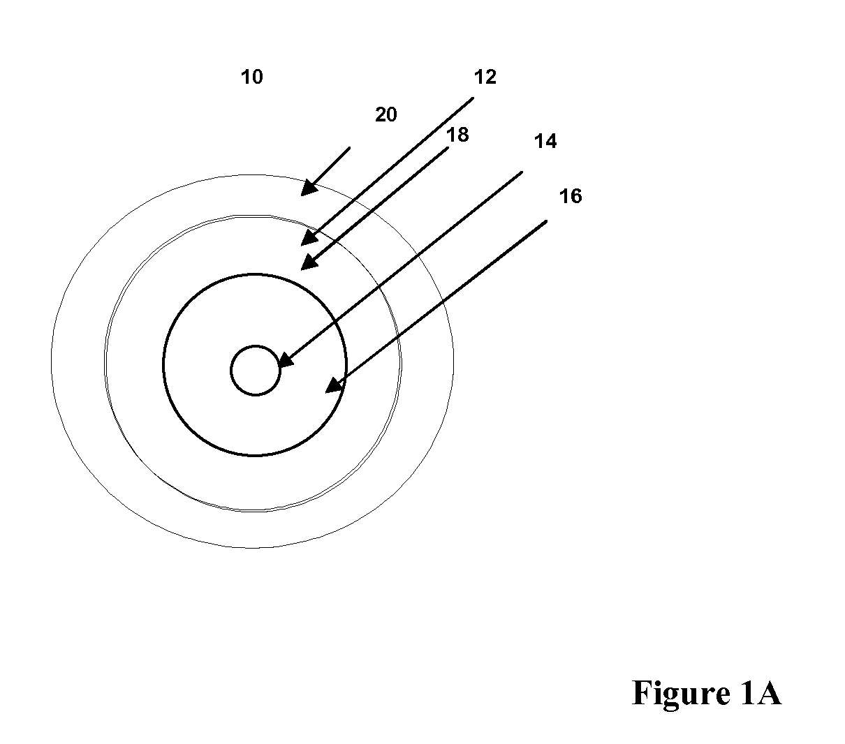
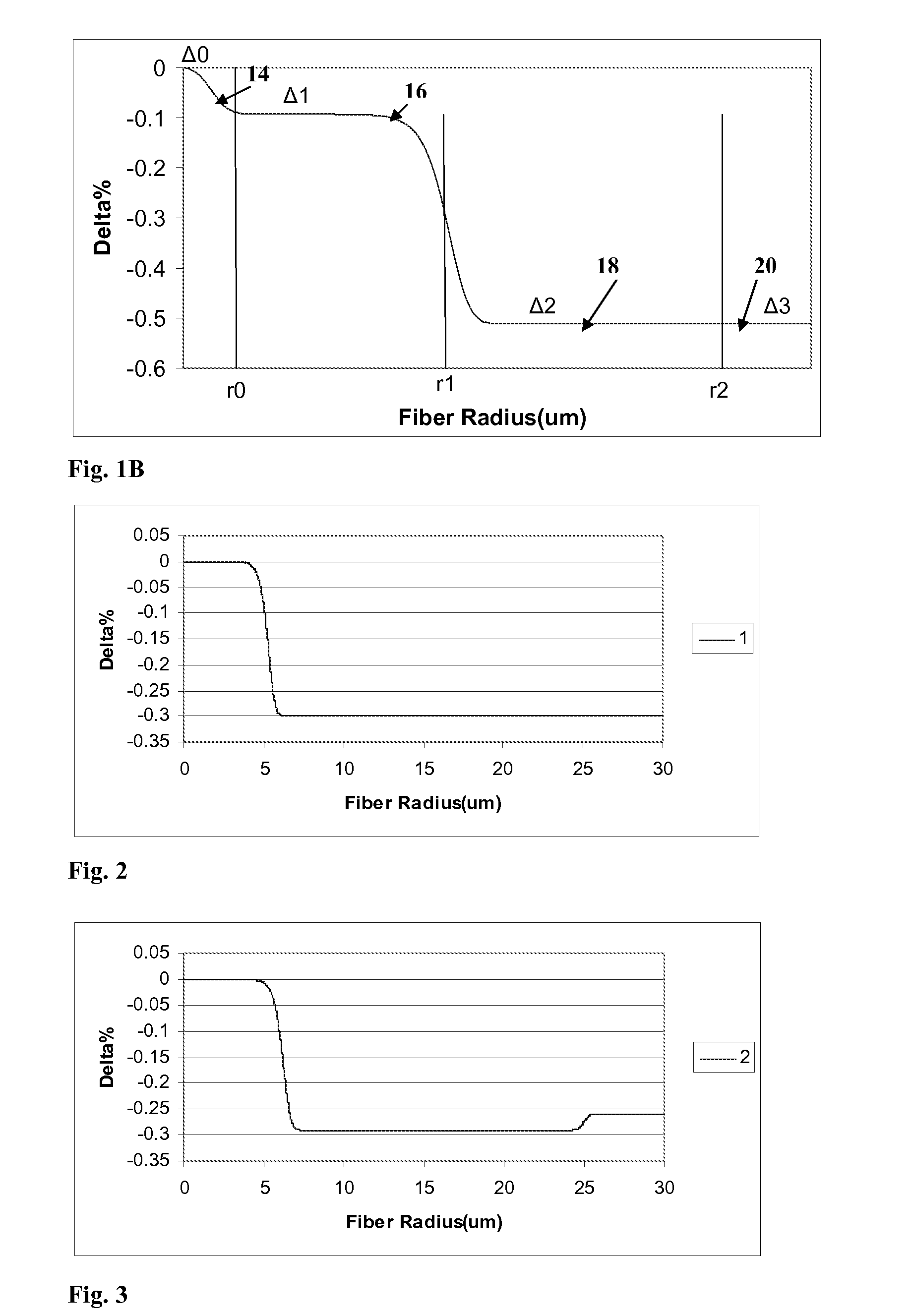
[0049]Tables 1-2 list characteristics of Examples 1-15 of one illustrative set of fiber embodiments. FIGS. 2-16 show the refractive index profiles corresponding to Examples 1-15, respectively. In these optical fiber embodiments of Examples 1-15, −0.5%≦Δ0=≦0% and Δ0max=≦0%; −0.065%≦Δ1(r=2.5 μm)≦0%, −0.065%≦Δ1max≦0.0%, −0.5%≦Δ2MIN≦−0.27%, −0.4%≦Δ3≦−0.2%, and r2 / r1 is 2.17≦r2 / r1≦5.7 and r20 may be somewhat larger or smaller than 0% (relative to silica), depending on whether updopants or downdopants are present in the center core region 14. Although some embodiments of the optical fibers 10 have alpha values between 12 and 25, optical fiber embodiments of Examples 1-9 have alpha values in the range of 13-15. Optical fiber embodiments of Examples 10-15 have alpha values of about 20.

[0050]The modeled profile parameters of these exemplary fibers are summarized in Table 1A. The values for r3 correspond to the outer diam...

examples 16-23

Fiber Examples 16-23

[0057]Modeled refractive index profiles of two embodiments of the optical fiber 10 of the present invention (Fiber Examples 16 and 17) are shown in FIG. 17. The optical fibers include a core 12 having an effective area of at about 110 μm2 at 1550 nm wavelength and a cladding 20 surrounding the core. The core 12 includes a pure silica central core region 14 extending radially outwardly from a centerline to a radius 0 μm≦r0≦2 μm, and a first annular core region 16 that extends to the outer radius r1, wherein r1 is about 5 μm. The second annular region 18 surrounds the first annular region and is down-doped relative to the first annular core region 16. The second annular region extends to the outer radius r2, wherein r2 is about 17 μm in Fiber Example 16 and about 25 μm in Fiber Example 17. Table 3A, below lists optical parameters of Fiber Examples 16 and 17.

TABLE 3AOptical parameters for Fiber Examples 16 and 17.PinArray atLat. Load atAeff atDispersion at2 m1550 nm...


PUM

PropertyMeasurementUnit
areaaaaaaaaaaa
outer radiusaaaaaaaaaa
radiusaaaaaaaaaa

Abstract

According to some embodiments an optical waveguide fiber comprises:(i) a Ge free core having an effective area of 90 μm2 to 160 μm2, at a 1550 nm wavelength, and α value 12≦α≦25, said core comprising:(a) a central core region extending radially outwardly from a centerline to a radius 0 μm≦r0≦2 μm, and having a relative refractive index percent profile Δ0(r) in % measured relative to pure silica, wherein −0.1%≦Δ0(r)≦0.1%, wherein the central core region has a maximum relative refractive index percent, Δ0MAX,(b) a first annular core region surrounding and directly adjacent to the central core region and extending to an outer radius r1, wherein 4.8 μm≦r1≦10 μm, and having a relative refractive index percent profile, Δ1(r) in % measured relative to pure silica, and a minimum relative refractive index, Δ2MIN, and the relative refractive index measured at a radius r=2.5 μm being:−0.15≦Δ1(r=2.5 μm)≦0, and Δ0MAX≧Δ1(r=2.5 μm);(c) a fluorine doped second annular region surrounding and directly adjacent to the first annular core region and extending to a radius 13 μm≦r2≦30 μm and having a negative relative refractive index percent profile, Δ2(r) in %, measured relative to pure silica,with a minimum relative refractive index percent Δ2MIN being:Δ2MIN≦Δ1(r=2.5 μm), and −0.7%≦Δ2MIN≦−0.28%;(ii) a cladding surrounding the core and having a relative refractive index percent Δc(r) in % measured relative to pure silica, and Δc(r)=Δ2MIN±0.3%;wherein the relative refractive index profile of the optical fiber is selected to provide attenuation of no more than 0.175 dB / km at the wavelength of 1550 nm.

Description

CROSS-REFERENCE TO RELATED APPLICATIONS[0001]This is a continuation-in-part of U.S. patent application Ser. No. 12 / 362,694 filed on Jan. 30, 2009, the content of which is relied upon and incorporated herein by reference in its entirety, and the benefit of priority under 35 U.S.C. §120 is hereby claimed.FIELD OF THE INVENTION[0002]The present invention relates generally to optical fibers, and particularly to large effective area optical fibers with pure silica core and low attenuation.TECHNICAL BACKGROUND[0003]Optical amplifier technology and wavelength division multiplexing techniques are typically required in telecommunication systems that provide high power transmissions for long distances. The definition of high power and long distances is meaningful only in the context of a particular telecommunication system wherein a bit rate, a bit error rate, a multiplexing scheme, and perhaps optical amplifiers are specified. There are additional factors, known to those skilled in the art, ...

Claims


Application Information

Patent Timeline
Patent Type & Authority Applications(United States)
IPC IPC(8): G02B6/036
CPCC03C13/046G02B6/02019G02B6/0281G02B6/02395G02B6/03627G02B6/0365G02B6/0283G02B6/028G02B6/036
Inventor BICKHAM, SCOTT ROBERTSONBOOKBINDER, DANA CRAIGLI, MING-JUNMISHRA, SNIGDHARAJ KUMARNOLAN, DANIEL ALOYSIUSTANDON, PUSHKAR
Owner CORNING INC
Why Eureka
Try Eureka