Method and apparatus for interference cancellation

a technology of interference cancellation and interference signals, applied in the field of interference cancellation, can solve the problems of reducing and interference signals that fall within the receive frequency band are usually a bigger problem, so as to reduce the performance requirement of a diplexer, reduce the cost, and reduce the performance required of a diplexer.

Active Publication Date: 2010-08-05
TELEFON AB LM ERICSSON (PUBL)
View PDF15 Cites 94 Cited by
  • Summary
  • Abstract
  • Description
  • Claims
  • Application Information

AI Technical Summary

Benefits of technology

[0007]It would be desirable to be able to reduce the performance requirements for a diplexer in a transceiver. To better address this concern and / or other concerns, in a first aspect of what is taught herein, an interference canceller between a transmit chain and a receive chain of a transceiver is proposed. The transceiver comprises a diplexer between the transmit chain and the receive chain. The interference canceller comprises a transmit chain tap, a receive chain coupler for coupling an interference compensation signal into the receive chain, and an interference signal processing path between the transmit chain tap and the receive chain coupler. The interference signal processing path comprises a filter having filter characteristics similar or corresponding to the filtering characteristics of a receive portion of the diplexer. The use of transmit signal cancellation in the receive path of a transceiver allows reducing the performance required of the diplexer filter, rather than eliminating the need for a diplexer filter altogether. The action of the diplexer and the active interference cancellation provided by the interference canceller supplement each other. Compared to previous solutions, the diplexer can be of reduced cost and reduced size and causes less insertion loss. The ability to use a simpler filter widens the technology choices available for the fabrication of the diplexer.
[0008]The diplexer, or duplex filter, separates the transmit and receive bands in the frequency-division duplex scheme for which the unit is designed. The filter of the interference canceller may be a bandpass filter, a high-pass filter, or a low-pass filter. The filter has filtering characteristics that are similar or corresponding to the filtering characteristics of the receive portion of the diplexer. This choice ensures that only (or largely) the transmitter noise falling into the receive band is passed to the receive chain coupler; this differs from previous solutions in which the aim is to remove the main transmit signal energy, not just the portion of the transmitter's energy appearing in the receive band. Such solutions attempt to improve the receiver's blocking performance, by reducing the amount of the high-power transmit signal appearing in the receive band, which de-senses (or ‘blocks’) the receiver when it attempts to receive weak signals. In the present invention, however, the aim is to improve the receiver's noise figure by removing the contribution of the transmitter's noise and intermodulation distortion which falls into the receive band. Furthermore, the filter of the interference canceller has a similar influence on the transmitter noise than the receive portion of the diplexer. It would be desirable that the signal coupled to the receive chain is an anti-phase cancelling signal such that vector cancellation of the transmit noise and intermodulation distortion occurs in the receive chain coupler.
[0009]The proposed solution attempts to reduce the performance required from a diplexer, not eliminate it altogether. The proposed solution removes the transmit noise and intermodulation distortion (IMD) which falls into the receive band and not the main transmit signal itself (although this may also be reduced, co-incidentally).

Problems solved by technology

The proposed solution attempts to reduce the performance required from a diplexer, not eliminate it altogether.
On the other hand, interference signals that fall within the receive frequency band are usually a bigger problem.

Method used


Image

  • Method and apparatus for interference cancellation
  • Method and apparatus for interference cancellation
  • Method and apparatus for interference cancellation

Examples


Embodiment Construction

[0036]For a complete understanding of the present invention and the advantages thereof, reference is now made to the following detailed description taken in conjunction with the Figures.

[0037]It should be appreciated that the various aspects of the invention discussed herein are merely illustrative of the specific ways to make and use the invention and do not therefore limit the scope of invention when taken into consideration with the claims and the following detailed description. It will also be appreciated that features from one embodiment of the invention may be combined with features from another embodiment of the invention.

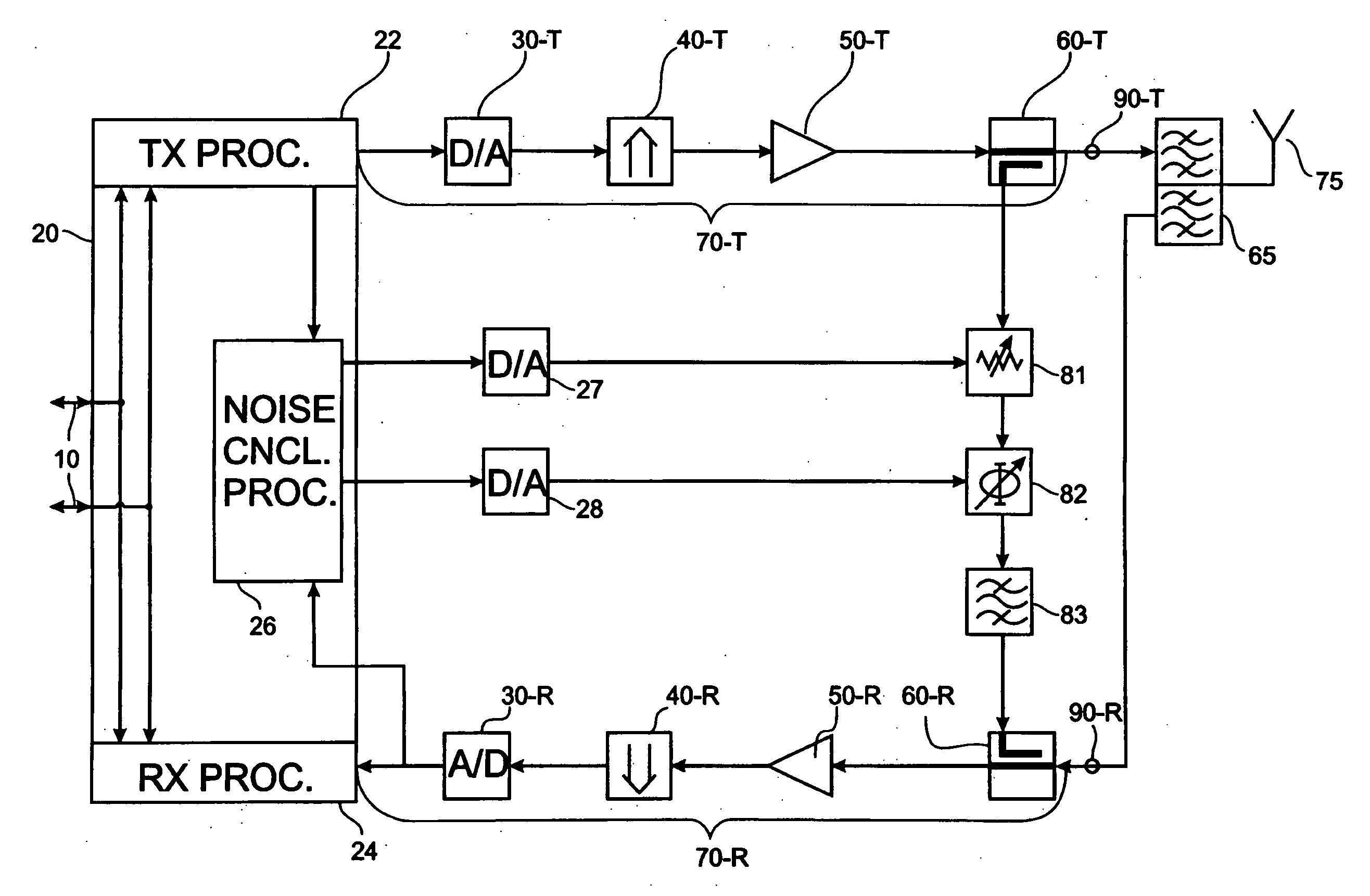
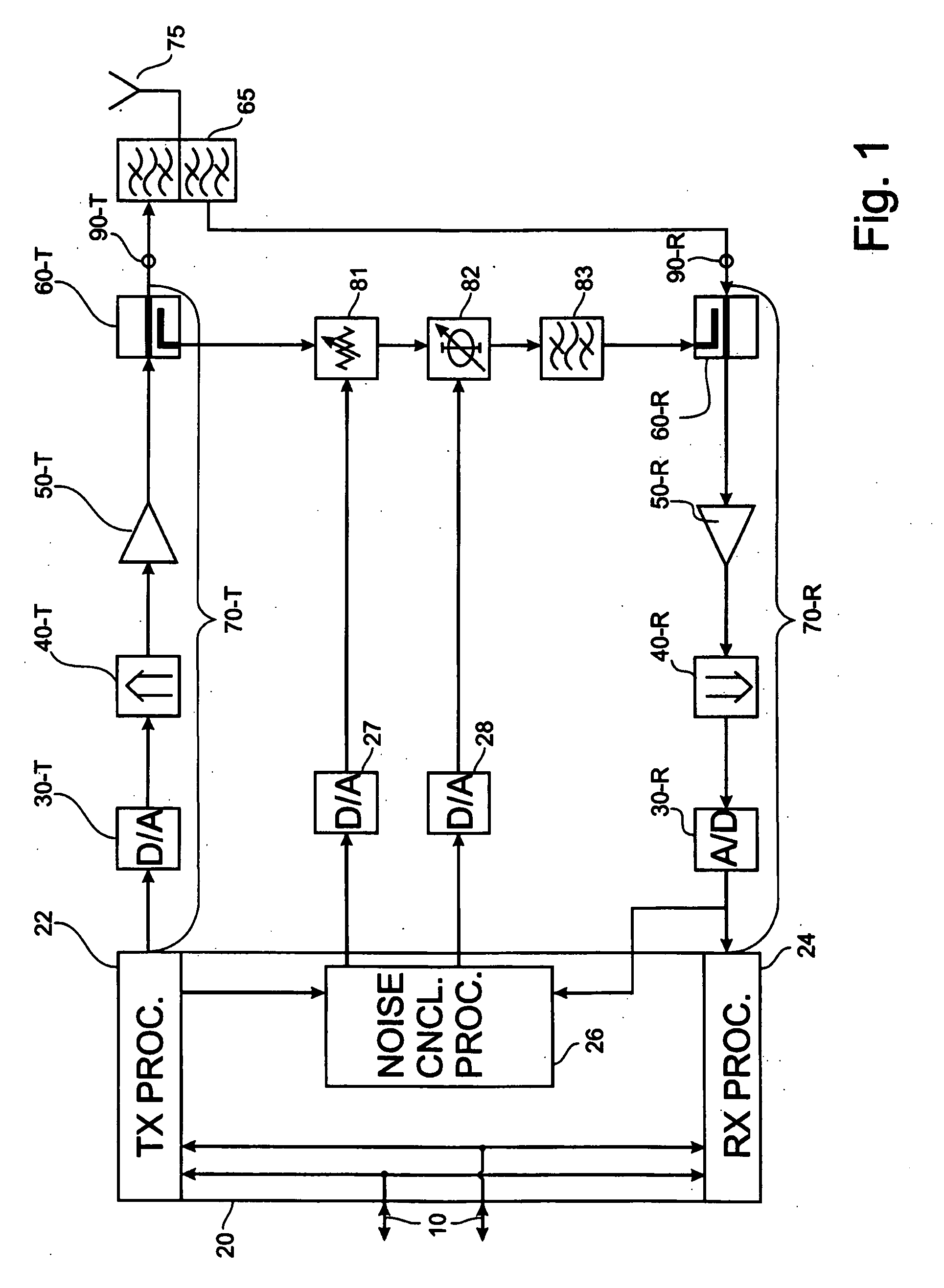
[0038]FIG. 1 shows a schematic block diagram of a transceiver. The transceiver comprises a transmitter that is illustrated in the upper part of FIG. 1, and a receiver that is illustrated in the lower part of FIG. 1. The transceiver has an interface for exchanging input / output data 10 with components external to the transceiver.

[0039]In the transmit direction...


PUM


Abstract

An interference canceller between a transmit chain and a receive chain of a transceiver is proposed to complement the action of a diplexer, or duplex filter, that is part of the transceiver. The interference canceller comprises a transmit chain tap, a receive chain coupler for coupling an interference compensation signal into the receive chain, and an interference signal processing path between the transmit chain tap and the receive chain coupler. The interference signal processing path comprises a filter having filtering characteristics similar or corresponding to the filtering characteristic of a receive portion of said diplexer. A corresponding method for interference cancellation is also proposed. Computer-program products for the manufacture of the interference canceller and the execution of the method are also proposed.

Description

FIELD OF THE INVENTION[0001]The application relates to an interference canceller in a radio transceiver. The application also relates to a method for interference cancellation in a radio transceiver.[0002]The application further relates to a computer program product enabling a processor to carry out the method for interference cancellation and to a computer program product useable for the manufacture of the interference canceller. Moreover, the invention relates to an antenna array comprising an interference canceller.BACKGROUND OF THE INVENTION[0003]Transceivers for radio communication that use the same antenna for transmission and for reception of radio signals often require a diplexer, or duplex filter. This is particularly true when the transceiver uses a frequency-division duplex scheme, i.e. the transmit and receive bands are at different frequencies.[0004]Duplex filters are often large and expensive because of their high performance requirements. For antenna arrays having sev...

Claims


Application Information

Patent Timeline
Patent Type & Authority Applications(United States)
IPC IPC(8): H04B15/00
CPCH04B1/525
Inventor KENINGTON, PETER
Owner TELEFON AB LM ERICSSON (PUBL)
Why Eureka
Try Eureka