Power Generation Plant Having Inert Gas Deaerator and Associated Methods

a technology of inert gas and degasification device, which is applied in the direction of liquid degasification, machine/engine, separation process, etc., can solve the problem that inert gas cannot be as effective at degasification of condensate, and achieve the effect of prolonging the life and service interval of components

Inactive Publication Date: 2010-08-12
SIEMENS ENERGY INC
View PDF10 Cites 30 Cited by
  • Summary
  • Abstract
  • Description
  • Claims
  • Application Information

AI Technical Summary

Benefits of technology

[0010]This and other objects, features, and advantages in accordance with the present invention are provided by a power generation plant comprising a steam turbine and an electrical generator driven thereby. A condenser may be downstream from the steam turbine. In addition, there may be a steam source and an inert gas source. A deaerator may be downstream from the condenser and may be operable to perform deaeration using the inert gas source. The deaerator may also be selectively operable to perform deaeration using the steam source. The use of inert gas may help to remove dissolved gases, such as carbon dioxide and oxygen, from condensed water. This may help to extend the lifetime and service intervals of components of the power generation plant.
[0011]Furthermore, the use of inert gas is particularly advantageous when the power generation plant is being started after a maintenance outage and may quickly remove non-condensable gasses from the deaerator and dissolved gases from the condensate. After such a maintenance outage, the condensate may be saturated with dissolved gasses, such as carbon dioxide. Since the steam to run the steam turbine is generated from the condensate, it will likewise be saturated with undesired impurity gases at the thermodynamic conditions of the deaerator and will not be as effective as inert gas at deaerating the condensate in the deaerator.

Problems solved by technology

Since the steam to run the steam turbine is generated from the condensate, it will likewise be saturated with undesired impurity gases at the thermodynamic conditions of the deaerator and will not be as effective as inert gas at deaerating the condensate in the deaerator.

Method used


Image

  • Power Generation Plant Having Inert Gas Deaerator and Associated Methods
  • Power Generation Plant Having Inert Gas Deaerator and Associated Methods
  • Power Generation Plant Having Inert Gas Deaerator and Associated Methods

Examples


Embodiment Construction

[0021]The present invention will now be described more fully hereinafter with reference to the accompanying drawings, in which preferred embodiments of the invention are shown. This invention may, however, be embodied in many different forms and should not be construed as limited to the embodiments set forth herein. Rather, these embodiments are provided so that this disclosure will be thorough and complete, and will fully convey the scope of the invention to those skilled in the art. Like numbers refer to like elements throughout, and prime notation is used to indicate similar elements in alternative embodiments.

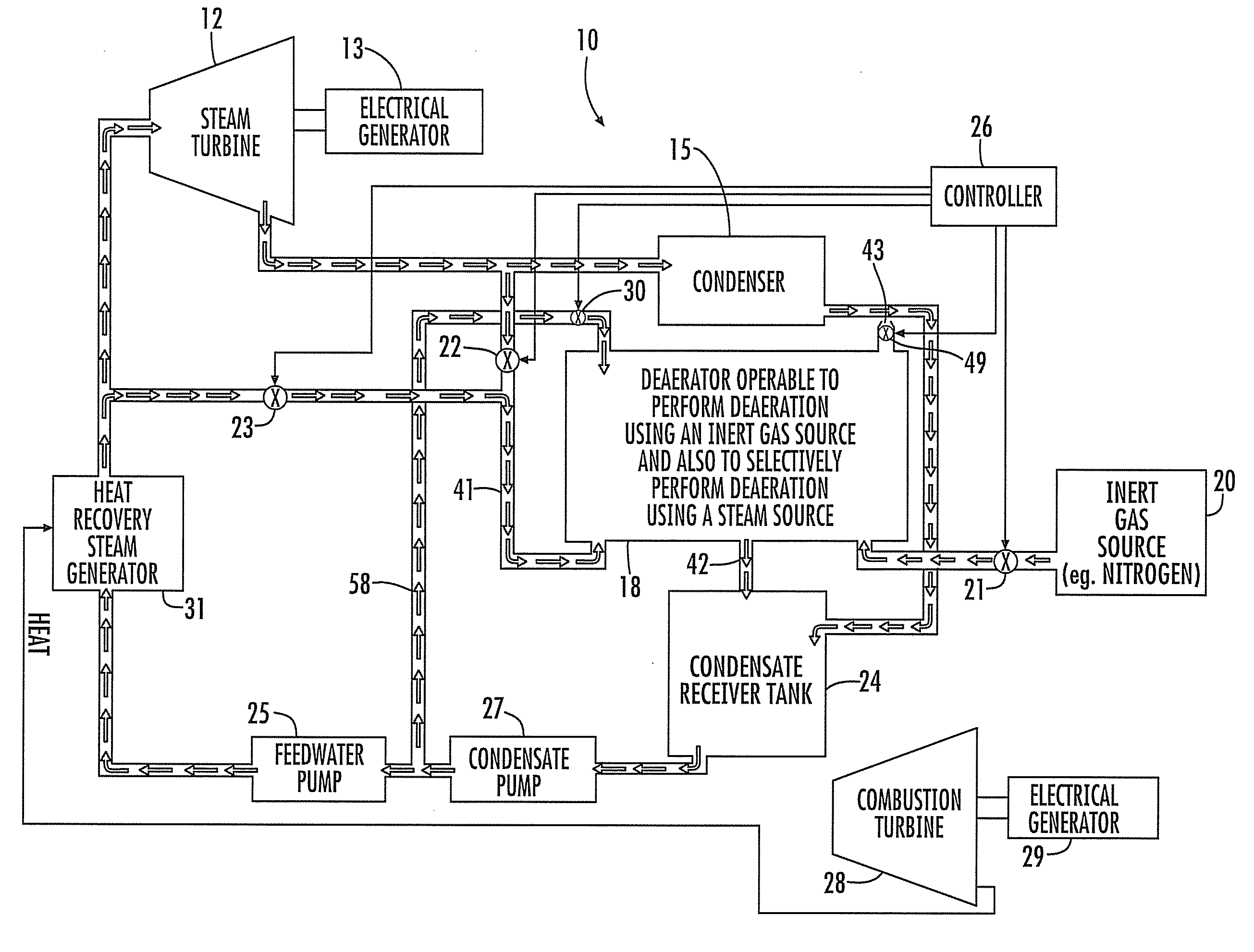
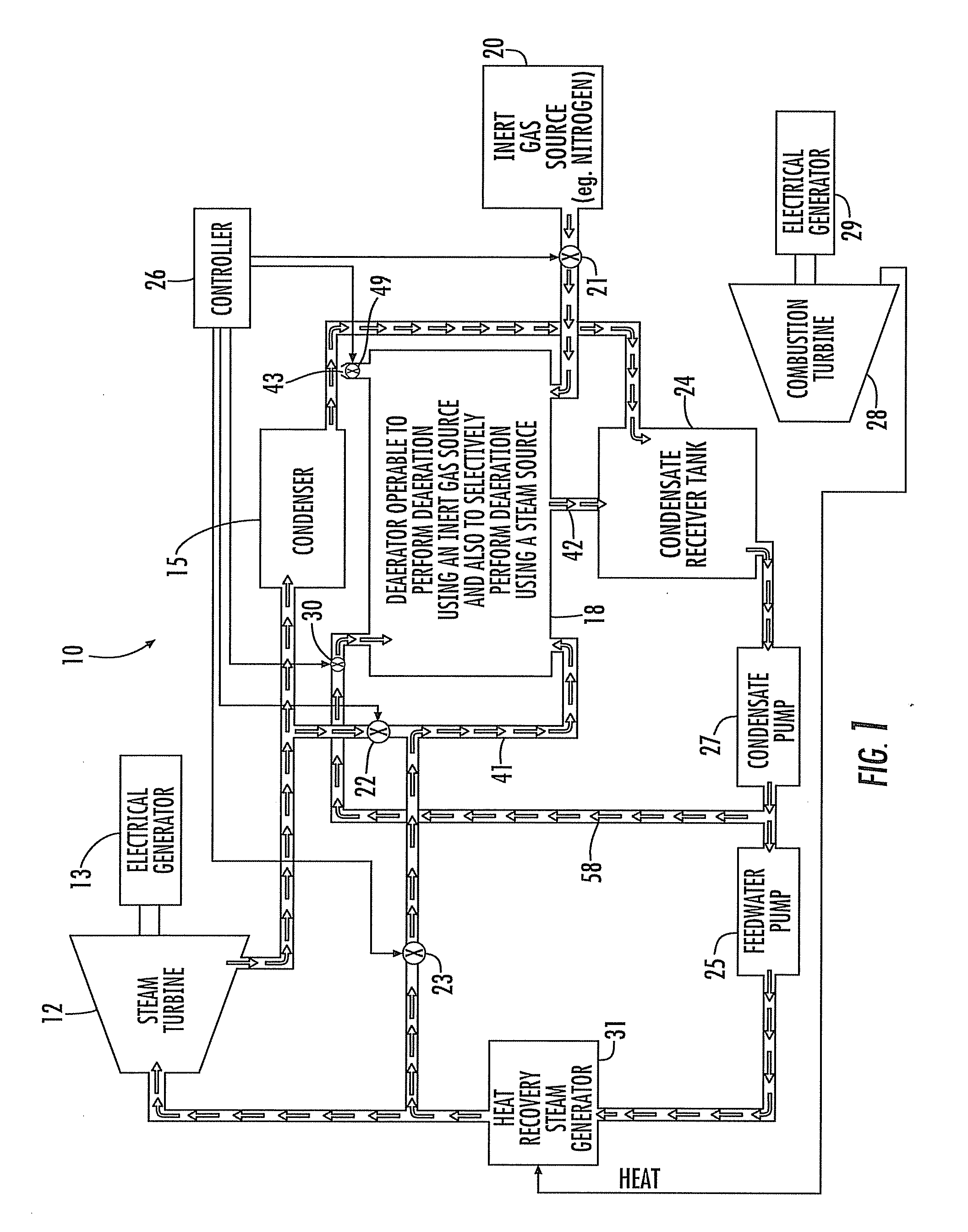
[0022]Referring initially to FIGS. 1-2, a power generation plant 10 is now described. The power generation plant 10 includes a steam turbine 12 and an electrical generator 13 driven thereby. A condenser 15 is coupled to the steam turbine 12 and receives a flow of steam therefrom. The condenser is illustratively an air-cooled heat exchanger in which the steam flows into tube...


PUM

PropertyMeasurementUnit
corrosiveaaaaaaaaaa
thermodynamic conditionsaaaaaaaaaa
pressureaaaaaaaaaa

Abstract

A power generation plant includes a steam turbine and an electrical generator driven thereby. A condenser is downstream from the steam turbine. Moreover, the power generation plant includes a steam source and an inert gas source. A deaerator downstream from the condenser and is operable to perform deaeration using the inert gas source and is also selectively operable to perform deaeration using the steam source.

Description

FIELD OF THE INVENTION[0001]The present invention relates to the field of power plants, and, more particularly, to deaerators for power plants and related methods.BACKGROUND OF THE INVENTION[0002]A power generation plant typically includes a source of feedwater, a steam generator or boiler to heat the feedwater until the feedwater becomes steam, and a steam turbine to be rotated by a flow of steam from the steam generator. The steam turbine is coupled to an electrical generator by a rotatable driveshaft to thereby generate electricity as the steam turbine rotates.[0003]After the flow of steam exits the steam turbine, it is directed into a condenser. The condenser cools the flow of steam until the flow of steam condenses back into liquid water, commonly called the condensate. The condensate may contain dissolved gasses. The dissolved gasses may be corrosive and corrode various metallic components of the power generation plant. Similarly, solid corrosion products may deposit on the su...

Claims


Application Information

Patent Timeline
Patent Type & Authority Applications(United States)
IPC IPC(8): F01K19/00F01K21/06B01D19/00
CPCB01D19/0015F01K23/10Y02E20/16B01D19/0063
Inventor ROBERTSON, TERI J.BELLOWS, JAMES C.
Owner SIEMENS ENERGY INC
Why Eureka
Try Eureka