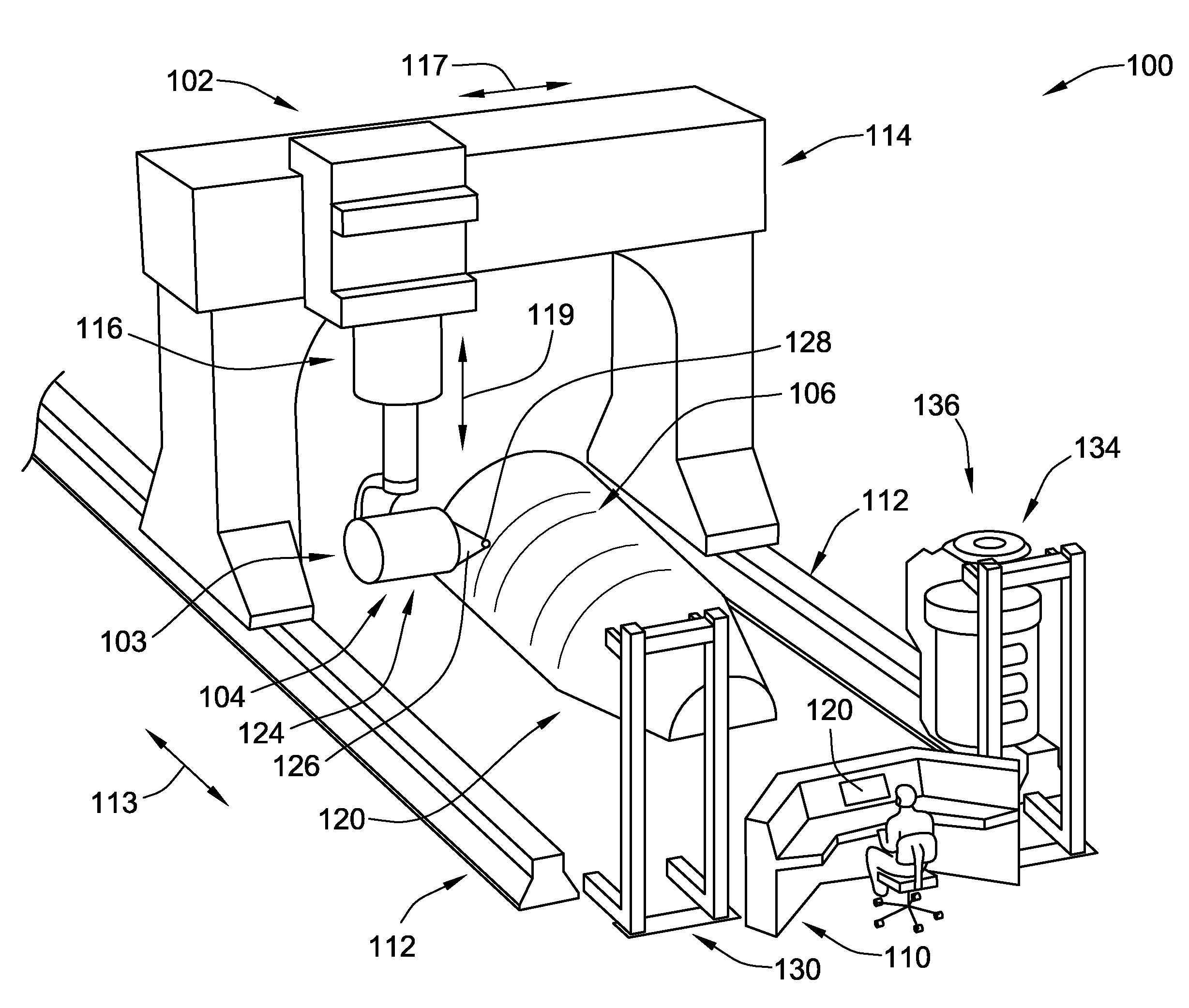
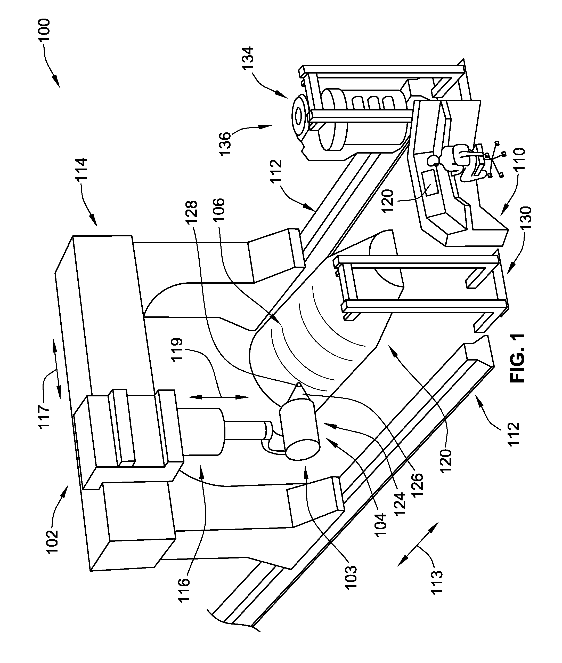
[0015]Embodiments of the present invention provide fiber delivery apparatuses for use in a fiber placement
system that provide fixed tow paths along which tows travel from a fiber spool toward a fiber placement head and more particularly a compaction roller of / attached to the fiber placement head. This arrangement eliminates the need for any fiber redirect mechanisms that redirect the tow paths or take up tows as they are dispensed from the fiber spools.
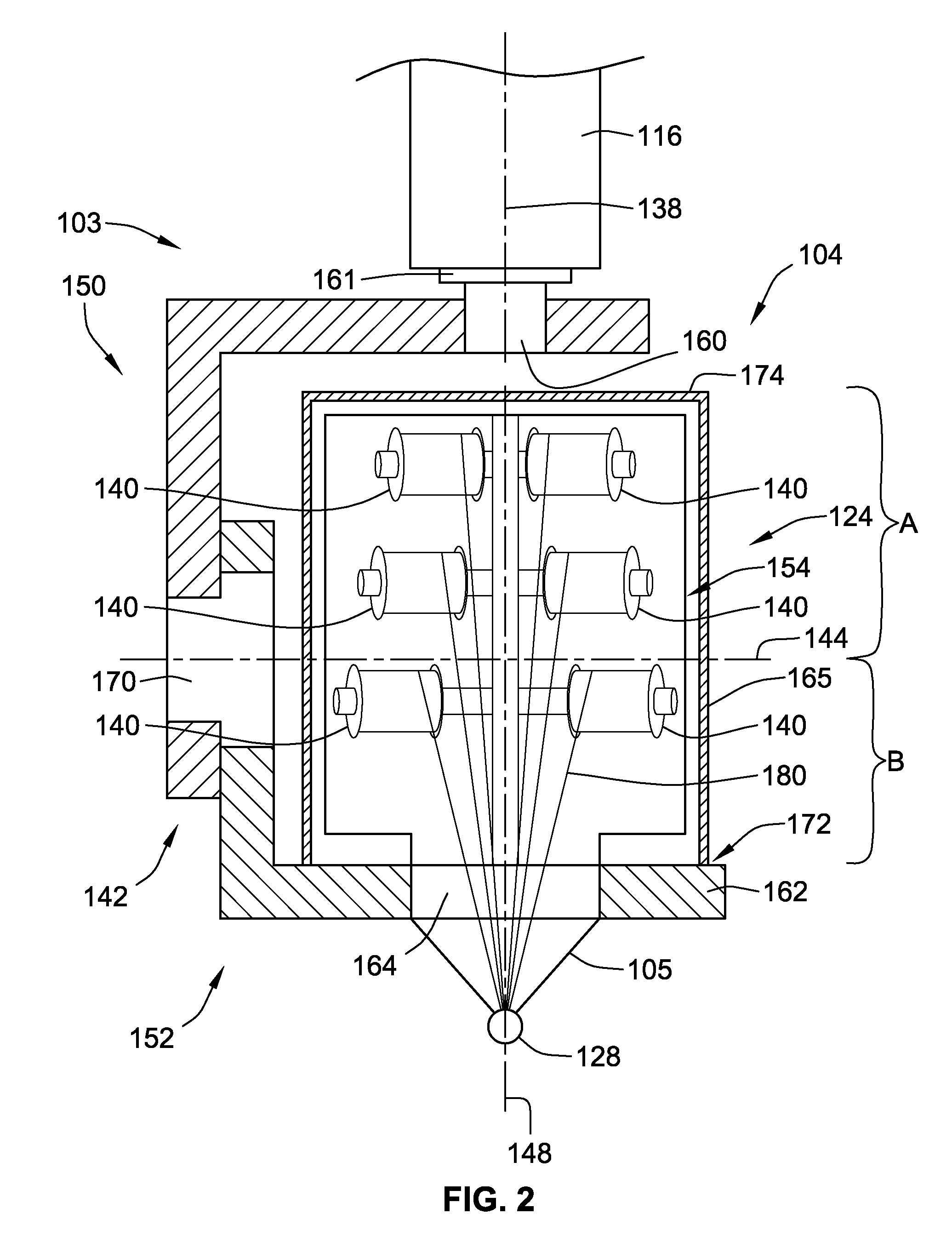
[0020]In one embodiment, at least a portion of the spool support structure is positioned on a first side of the
wrist articulating axis and the compaction roller is on an opposite second side of the
wrist articulating axis. More particularly, the compaction roller is on a first side of and at least one of the spools is on a second, opposite, side of a plane that is orthogonal to the
head rotation axis and that includes the
wrist articulation axis. This arrangement prevents the connection of the fiber delivery apparatus from being positioned at a distal end thereof such that the positioner device and the connection to the fiber delivery apparatus extends a length or
footprint of the fiber delivery apparatus increasing the minimum size of a female cavity in which the combined fiber delivery apparatus may be used.
[0024]In one embodiment, all components of the fiber delivery apparatus rotatable about the wrist articulation axis relative to the first wrist element lie within an imaginary boundary defined by a circle centered about the wrist articulation axis having a
radius defined between the wrist articulation axis and the compaction roller. This arrangement allows the fiber delivery apparatus to be placed into a female cavity and rotated about the wrist articulation axis with less fear of contacting or engaging a surface of a female tool.
[0026]In a further embodiment of the invention, a fiber delivery apparatus including an articulating wrist, a creel
assembly, a fiber placement head and a compaction roller is provided that is configured to balance the foot print of the apparatus on opposite sides of a wrist articulation axis to increase
operability within smaller female tools. The articulating wrist apparatus includes first and second wrist elements operably coupled to one another for pivotable movement therebetween about a wrist articulation axis. The creel assembly stores a plurality of fiber spools therein. The creel assembly mounts to the second wrist element for rotation about the wrist articulation axis relative to the first wrist element. The fiber placement head mounts to the second wrist element. The fiber placement head is maintained in a substantially
fixed position relative to the fiber spools. The compaction roller attaches to the fiber placement head. The compaction roller is always axially spaced from at least one of the fiber spools along an offset axis that is generally perpendicular to both the wrist articulation axis and an axis of rotation of the compaction roller and the wrist articulating axis is axially interposed along the offset axis between the at least one of the fiber spools and the compaction roller.
[0037]Accordingly, an embodiment, the self-contained fiber
delivery system, having the complete product
kinematics, the Cartesian positioning instructions and the fiber tow delivery specifications contained within, may move unilaterally in relation to the tool, mold or rotatable mandrel, which may be mounted on a rotatable or articulating platform, yet require no movement, manipulation or articulation to complete the desired
product design or configuration. The absence of need for a coordinating or reciprocal movement by the tool, mold or rotatable mandrel, relieves the manufacturer of the time and expense of creating or modifying or
synchronizing any hardware or
software controlling the tool, mold or rotatable mandrel for its use in the manufacture of the desired
product design or configuration.
[0050]The apparatus may include a creel controller controlling creel events such as displacement of material from the at least two spools. The internal autonomous controller and creel controller are mounted on, such as within, the self-contained creel assembly and the internal autonomous controller, creel controller and positioner controller control their respective devices based on a CNC master design. Further, the internal autonomous controller and creel controller receive positioning information from the positioner to further facilitate control of their respective devices.

